Flowserve BUSwitch with Foundation Fieldbus Communications Protocol User Manual
Page 4
AX
ENIM0048-01 (Firmware Rev. Nov. 12 99) (AUTO-48) 11/01
Page 4 of 16
©2001, Flowserve Corporation,
Springville, UT
Flowserve Corporation
1350 South Mountain Springs Parkway
Phone: 801
489 2233
Flow
Control
Division Springville,
Utah
84663
Facsimile:
801
489
2228
Automation
Business
Unit www.flowserve.com
Email:
Automax Valve Automation Systems
Product Specification
8. Using the DO-1.OUT_D value parameter (and DO-
2.OUT_D for dual coil mode), stroke the valve
(Discrete 0 = de-energized; Discrete 1 = energized)
and set limit switches, referring to “Adjustment of
Switch Cams” section. Circuit board mounted LED’s
light when switches are tripped.
9. This is the minimum configuration to operate the
actuator and read valve position. Refer to
F
OUNDATION
Fieldbus standards for DO and DI blocks
to establish more sophisticated control strategies.
Refer to the block sections in this manual for more
information on BUSwitch™ functionality.
Mechanical Installation
BUSwitch™ Mounting:
Installation is best performed with Flowserve NAMUR
mounting kits. These kits allow direct mounting of the
BUSwitch™ shaft to the actuator pinion without a coupler.
The NAMUR mounting kits will work with any actuator
conforming to the NAMUR standard for accessory
mounting hole locations and pinion dimensions. Simply
attach the bracket to actuator and BUSwitch™ to the
bracket with the included fasteners. The BUSwitch™
shaft features an integral alignment pin that engages the
tapped pinion hole. Flowserve also offers a full line of
non-NAMUR mounting kits.
Spool and Tubing Configuration:
The following instructions apply to BUSwitch™ configured
with integral pilot valves and spool valve. For non-integral
pilot/spool valves, follow manufacturer's instructions for
piping.
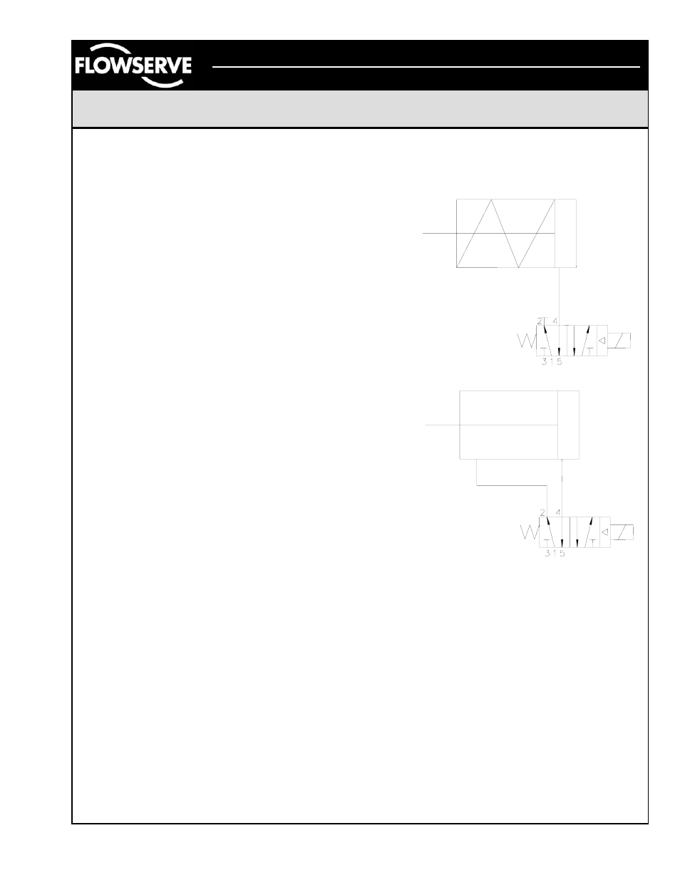
1. For spring return actuators, a 4-way spool valve is
provided with port #2 plugged. For double acting
actuators, the same valve is provided with no plugs.
Make sure the correct spool is selected before
installing tubing. (Note: the Flowserve APS2 purge
module can be supplied on spring return actuators to
purge the spring chamber with supply air.)
2. Make sure all air pressure is removed before installing
tubing.
3.
Attach tubing according to Figures 1 or 2 below,
depending upon application. Attach supply tubing to
Port 1 and use 3 and 5 for exhaust.
4. To prolong actuator life use only clean, dry plant air.
Lubricated air is not required, although it is
recommended, particularly for high cycle applications.
Lubrication
All BUSwitch™ spool valves are pre-lubricated and will
operate dry (with no additional lubrication). The use of
lubricated air will not interfere with the functioning of the
BUSwitch™. If air lubrication is used, the oils listed below
are popular, easily obtainable, fluids that are
recommended for use with the BUSwitch
™ spool valve:
Gulf Harmony 47, Mobil DTE Medium, Shell Tellus 29,
Texaco Rondo B, Sohivis 47 and Sunnis 921. Many other
lubricants are acceptable providing they do not contain
detergents that will attack Buna N or Viton Seals.
Figure 1
Figure 2