Reverse-acting and split-range, Dampers, I/p unit, pm15e – Flowserve PM15E Electro-Pneumatic Valve Positioner User Manual
Page 6: Worcester controls
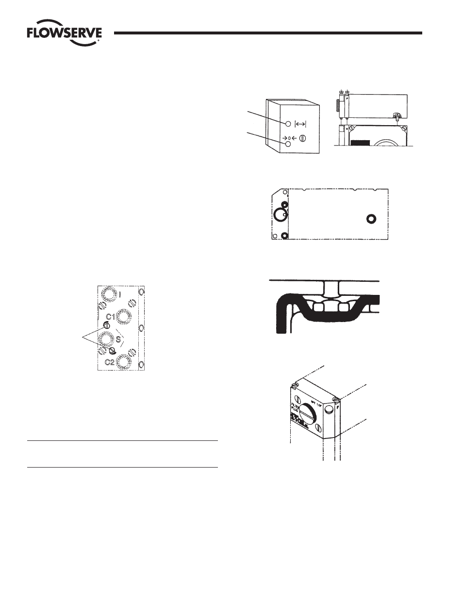
9. REVERSE-ACTING
AND SPLIT-RANGE
Reverse-Acting
For reverse-action operation, invert cam. Also reverse connections C1
and C2. For single-acting actuators, move actuator connection from
C2 to C1 and plug C1.
Split-Range
For split-range, reposition the cam, noting the markings on the cam:
for 4-12 mA, use initial 50% zone; for 12-20 mA, use 51–100% zone.
10. DAMPERS
The standard built-in dampers (5) located on the connecting block
provide a simple means of adjusting the actuator travel speed.
For maximum actuator travel speed, dampers shall be adjusted to
minimum damping position.
Double-Acting Actuators – Adjust only OUTLET damper; set SUPPLY
damper in minimum damping position.
Single-Acting Actuators – Adjust both dampers for desired operation.
11. I/P UNIT, PM15E
I/P unit is mounted directly on top of the positioner unit. No external
air supply is needed since the I/P unit is supplied with air from the
positioner unit.
The I/P unit is equipped with a built-in 30 micron filter (Figure 4).
CAUTION: Do not operate the unit without filter and filter plug
installed. Do not unscrew filter plug when the positioner is
pressurized.
Span and zero for the I/P converter is factory set and should not
require adjustment.
I/P Calibration
Check I/P output by connecting gauge to port P.
•
Adjust Zero on screw 2.
•
Adjust Span on screw 1.
Flow Control Division
Worcester Controls
6
Model PM15E Electro-Pneumatic Valve Positioner
WCAIM2017
5
1
Figure 1
Figure 2
Figure 3
Figure 4
2