Automax logix 3200iq digital positioner, Startup – Flowserve Logix 3200IQ Digital Positioner User Manual
Page 8
Flowserve Corporation
1350 N. Mountain Springs Parkway
1978 Foreman Dr.
Flow Control Division
Springville, Utah 84663-3004
Cookville, TN 38501
www.flowserve.com
Phone: 801 489 2233
Phone: 931 432 4021
FCD AXAIM3200-00 9/04
Page: 8 of 32
© 2004, Flowserve Corporation, Printed in USA
Automax Logix 3200IQ Digital Positioner
Installation, Operation and Maintenance Instructions
Cable Requirements
The Logix 3200IQ digital positioner utilizes the HART
Communication protocol. This communication signal is
superimposed on the 4-20 mA current signal. The two
frequencies used by the HART protocol are 1200 Hz and
2200 Hz. In order to prevent distortion of the HART
communication signal, cable capacitance and cable length
restrictions must be calculated. The cable length must be
limited if the capacitance is too high. Selecting a cable
with lower capacitance/foot rating will allow longer cable
runs. In addition to the cable capacitance, the network
resistance also affects the allowable cable length.
In order to calculate the maximum network capacitance,
use the following formula:
Equation 2
To control cable resistance, 24 AWG cable should be used
for runs less than 5000 feet. For cable runs longer than
5000 feet, 20 AWG cable should be used.
Intrinsically Safe Barriers
When selecting an intrinsically safe barrier, make sure the
barrier is HART compatible. Although the barrier will pass
the loop current and allow normal positioner control, if
not compatible, it may prevent HART communication.
Startup
Logix 3200IQ Local Interface Operation
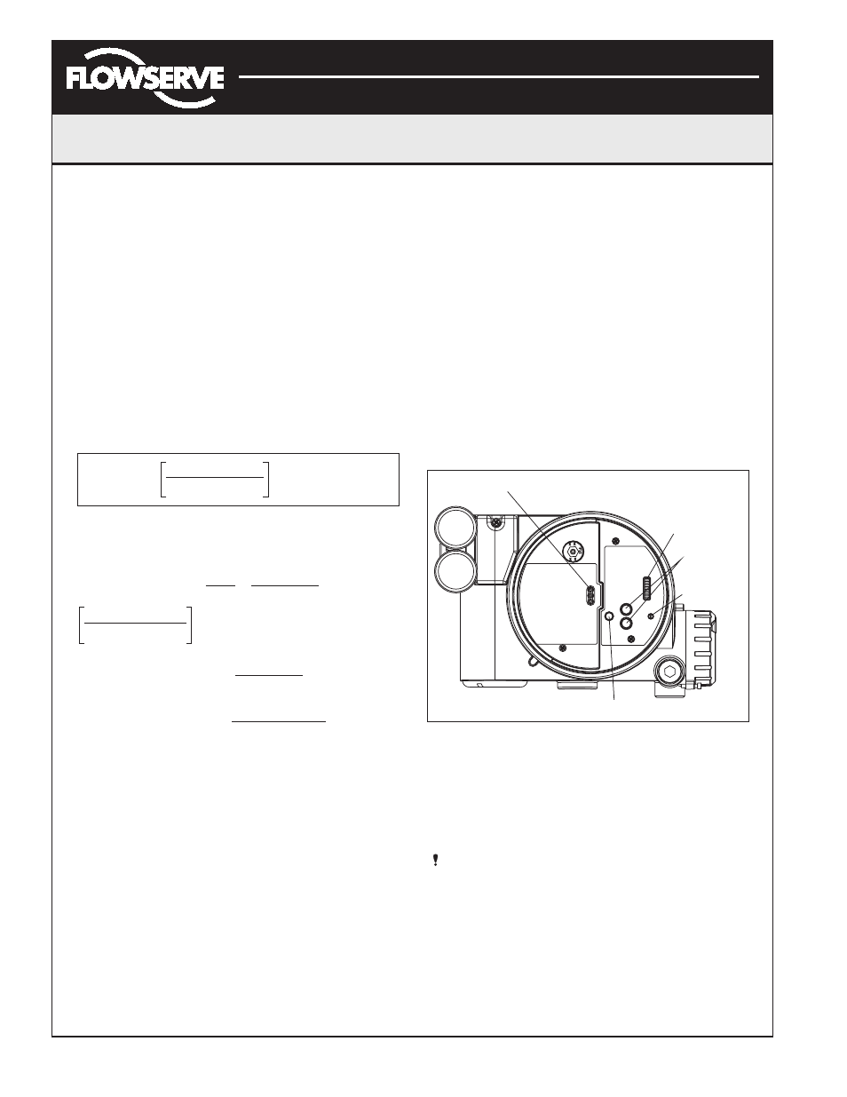
The Logix 3200IQ local user interface (Figure 11) allows
the user to configure the basic operation of the positioner,
tune the response and calibrate the positioner without
additional tools or configurators. The Local interface
consists of a QUICK-CAL button for automatic zero and
span setting, along with two jog buttons (
↑
and
↓
) for
spanning valve/actuators with no fixed internal stop in the
open position. There is also a DIP switch block containing
eight switches. Seven of the switches are for basic
configuration settings and one is for calibration options.
There is also a rotary selector switch for adjusting the
positioner gain settings. For indication of the operational
status or alarm conditions there are also three LEDs on
the local user interface.
Figure 11: Local User Interface
Initial DIP Switch Settings
Before placing the unit in service, set the DIP switches in
the Configuration and Cal boxes to the desired control
options. A detailed description of each DIP switch setting
follows.
NOTE: The Logix 3200IQ positioner reads the DIP
switch settings each time the QUICK-CAL button is
pressed. If a HART handheld or Flowserve PC software
is used to configure and then calibrate the positioner,
the DIP switches are not read. The auto-tune
adjustment switch labeled “GAIN” is always live and
can be adjusted at any time.
C
network
(
µ
F)
≤
- 0.0032
65
(R
barrier
+ R
wire
+ 390)
LEDs
DIP Switch Block
Jog Buttons
Rotary
Selector
Switch
QUICK-CAL Button
Example:
R
barrier
= 300
Ω
R
wire
=
50
Ω
C
cable
= =
- 0.0032 = 0.08
µ
F = C
max network
(
µ
f)
=
Maximum Cable Length
Maximum Cable Length
=
= 3636 ft
65
(300 + 50 + 390)
22 pF
foot
0.000022
µ
F
foot
C
max network
(
µ
F)
C
cable
0.08
µ
F
0.000022
µ
F/foot