System check-out, Wiring to the telephone switchboard – GAI-Tronics 495-001 Mine Dial / Page Phone Interface Cabinet User Manual
Page 12
Pub. 42004-198D
Model 495-001 Mine Dial/Page Phone Interface Cabinet
Page: 12 of 22
f:\standard ioms - current release\42004 instr. manuals\42004-198d.doc
10/11
System Check-Out
Wiring to the Telephone Switchboard
All connected telephone pairs, tip and ring, should have approximately 48 V dc across them at the
interface cabinet terminals, measured without the Interface PCBA assemblies installed.
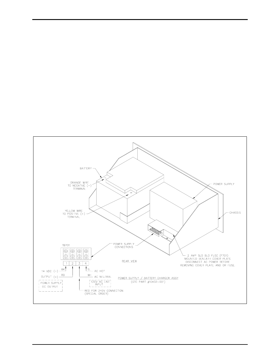
AC Power Supply/Metering Assembly and Battery Installation
N
OTE
: The ac power supply/battery charger should be powered-up and checked out prior to the
connection of the battery. Care should be taken to ensure that the battery connectors are not shorted
together or to the chassis before the unit is connected to ac power.
Install the stand-by battery in the rear of the Power Supply/Metering assembly as shown in Figure 9.
Connect the orange wire to the battery negative (-). Allow the yellow wire to remain disconnected until
power supply has been checked out.
Figure 9. Power Supply/Battery Charger Assembly