GAI-Tronics 495-001 Mine Dial / Page Phone Interface Cabinet User Manual
Page 4
Pub. 42004-198D
Model 495-001 Mine Dial/Page Phone Interface Cabinet
Page: 4 of 22
f:\standard ioms - current release\42004 instr. manuals\42004-198d.doc
10/11
The Model 495-001 Phone Interface Cabinet contains the following items:
Qty Part
No. Description
8
10428-001
PCBA Rack Assembly (each holding ten Telephone Line Interface Assemblies)
1
10432-001
Power Supply/Metering Panel Assembly
1 10431-001 All-Call/Merge
Assembly
1
10430-001
DC Power Transfer Assembly
1
10429-001
Housing for All-Call/Merge and DC Transfer Assemblies
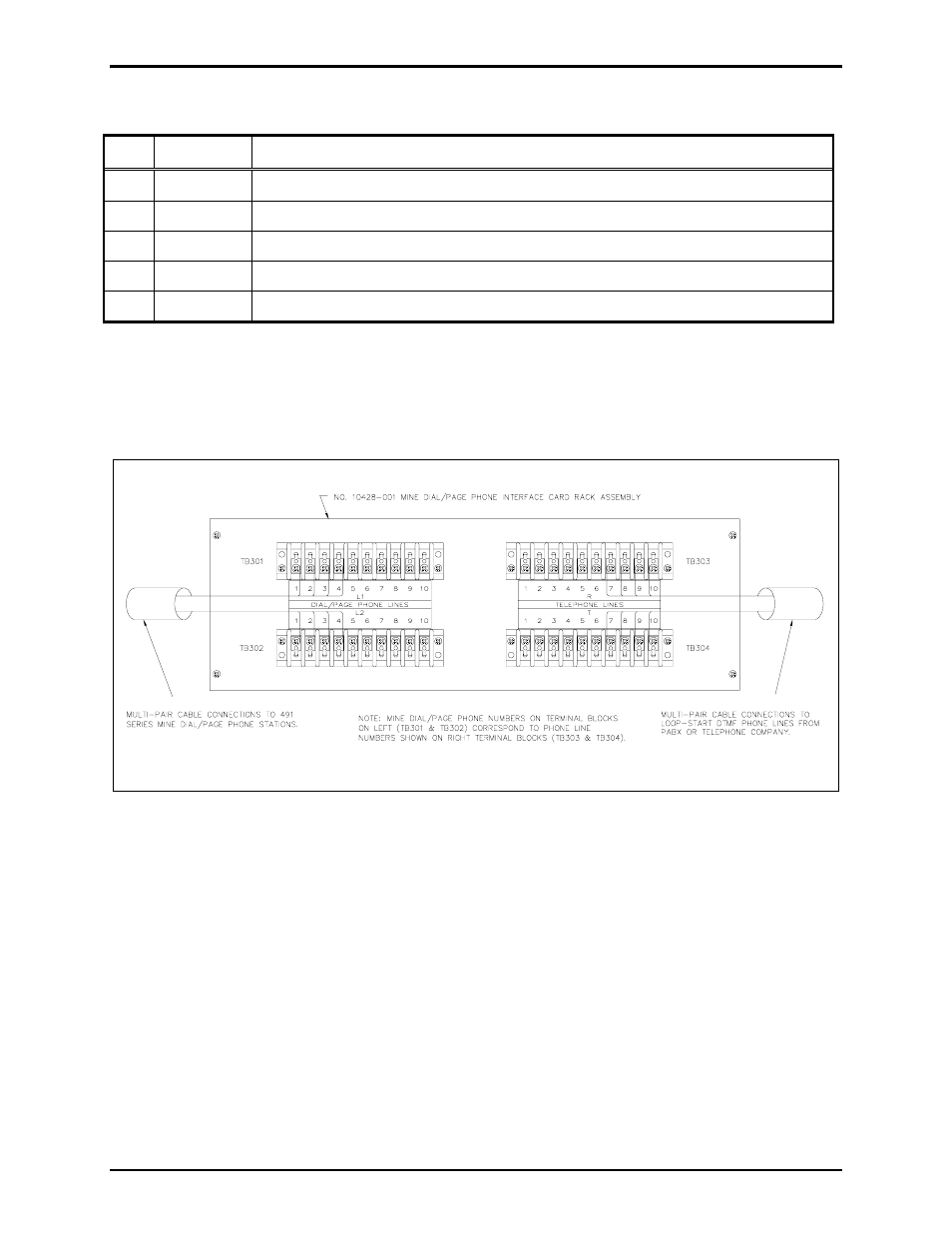
Each PCBA Rack assembly occupies the space of a 5.25
× 19-inch rack panel and includes four terminal
blocks on the rear surface. The four terminal blocks include two marked DIAL/PAGE
P
HONE
L
INES
to
connect ten pairs of wires from ten Mine Dial/Page Phones; and two marked T
ELEPHONE
L
INES
to
connect ten pairs of wires to the telephone switchboard. See Figure 3.
Figure 3. Wiring Diagram for 10428-001 Dial/Page Phone Interface Card Rack Assembly
The line number of a DIAL/PAGE
P
HONE
L
INE
S is coordinated with the T
ELEPHONE
L
INE
S number and
the Interface Assembly position. Mine Phone Line 1 and Telephone Line 1 are both wired to the Interface
assembly plugged into slot 1. A fifth terminal block inside the PCBA Rack assembly is used to
interconnect multiple rack assemblies and to connect to the All-Call/Merge assembly.