84505-202 wall-mount stanchion installation – GAI-Tronics 234WM Wall-Mount Stanchion Assembly User Manual
Page 3
Pub. 42004-308F
Model 234WM Wall-Mount Stanchion Assembly
Page:
3 of 12
f:\standard ioms - current release\42004 instr. manuals\42004-308f.doc
05/11
Model 84505-202 Wall-Mount Stanchion Installation
1. Remove and save the two tamper-resistant screws at the top of the stanchion. See Figure 1.
N
OTE
: GAI-Tronics Model 233-001 Security Screwdriver (sold separately) is required to remove
tamper-resistant screws.
2. Remove the wall-mounting assembly from the front panel assembly. Refer to Figure 1. Detach the
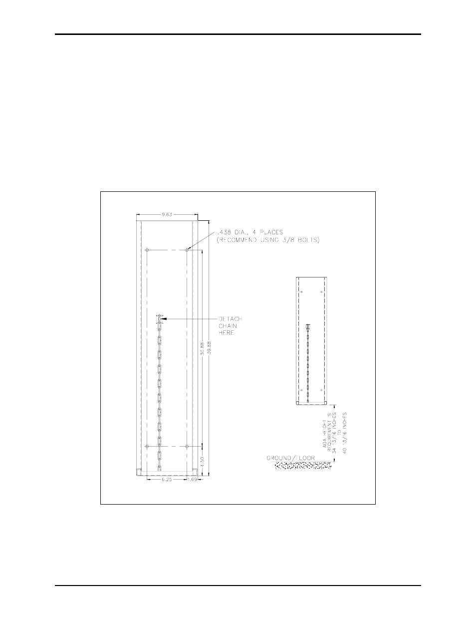
chain from the wall-mounting assembly. See Figure 2.
3. Enlarge the conduit entry pilot hole(s) to be used for the stanchion power cables. See Figure 3.
4. Fasten the wall-mounting assembly to a wall or flat surface that can support at least 50 pounds, using
3/8-inch bolts. Refer to Figure 2 for mounting hole dimensions and ADA height requirements.
Figure 2. Wall Mounting Instructions