001 or 531a strobe installation – GAI-Tronics 234WM Wall-Mount Stanchion Assembly User Manual
Page 7
Advertising
Pub. 42004-308F
Model 234WM Wall-Mount Stanchion Assembly
Page:
7 of 12
f:\standard ioms - current release\42004 instr. manuals\42004-308f.doc
05/11
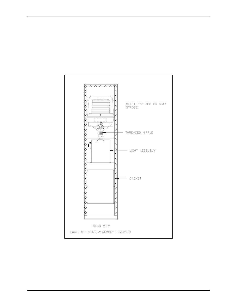
Model 530-001 or Model 531A Strobe Installation
1. Insert the strobe’s seven 15-foot wires through the stanchion’s threaded nipple, and allow the wires to
extend to the bottom of the stanchion. See Figure 6.
2. Screw the strobe onto the threaded nipple.
3. Separate the orange and violet wires necessary for the telephone connection and extend those wires
through the stanchion cutout for the telephone.
Figure 6. Strobe Assembly
Advertising