GAI-Tronics SSM110 Card Rack Assembly User Manual
Page 23
Pub. 42004-669L2E
SSM110 Card Rack Assembly Installation, Operation, Maintenance Manual
Page: 21 of 26
\\s_eng\gtcproddocs\standard ioms - current release\42004 instr. manuals\42004-669l2e.doc
07/07
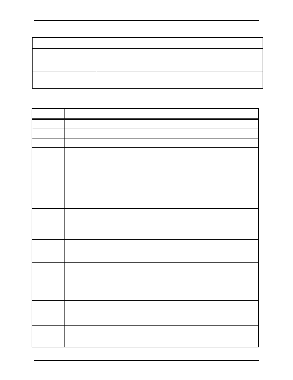
Troubleshooting the Card Rack
Symptom Action
Power LEDs on MCU card
do not illuminate.
Verify proper connection of ac power cord. Verify ac power is applied.
Verify the MCU is fully seated in the card rack.
Call for service of the power supply.
Plug-in cards do not operate
in one of the slots.
Check slot with a known good plug-in card.
Call for service of the card rack backplane.
Master Control Unit (MCU) Status Indicators
LED Description
(When
ON)
-12V
The card rack is providing –12 volts dc to the MCU.
+12V
The card rack is providing +12 volts dc to the MCU.
+5V
The card rack is providing +5 volts dc to the MCU.
BEEP
(red) This LED simulates the CPU module speaker function. The LED emits light instead of a
speaker emitting sound.
N
OTE
1: The LED may flash ON briefly when the PC begins booting, otherwise, this
LED is OFF. If applicable, your system manual lists situations where this LED should
be ON.
N
OTE
2: If the CPU Module detects an error during boot-up, this LED will flash more
than once. In this error condition, the CPU Module generates, a one-time “beep code” to
aid in diagnosing the fault. Momentarily pressing the reset button will cause the beep
code to repeat.
LINK
Shows Ethernet network status. The MCU has established a communications link with
another Ethernet network device.
ACT
Shows Ethernet network status. The MCU detects activity on the attached Ethernet
cable.
BP
(red)
The MCU is using the data bus in the card rack.
The card rack is sometimes referred to as “backplane,” which gives this LED its
abbreviation (BP).
SPD
This LED operates in conjunction with LINK LED to indicate the speed of the Ethernet
network connection.
LINK
(On)
SPD
(Off)
=
10 Mb Ethernet connection
LINK
(On)
SPD
(On)
=
100 Mb Ethernet connection
LINK
(Off)
SPD
(On/Off)
= no network connection established
SEC
(red)
The MCU is accessing the CompactFlash
®
card connected to the secondary IDE
controller.
PRI
(red)
The MCU is accessing the hard disk drive connected to the primary IDE controller.
B7,
B6,
B5,
B4,
B3,
B2,
B1,
or
B0
These LEDS are referred to as the Port 80 LEDs. They are used to show diagnostic
information that can be used by factory trained technicians as a troubleshooting aid.