Hansol 520F User Manual
Page 7
The microcontroller automatically detects the video board installed in your
system. When you turn on the monitor, the Micro controller first checks the
display mode memory stored in the user setting area and the factory presetting
area.
The microcontroller has memory capacity to store 24 different display modes
including timing formats and display settings. This memory capacity is
divided into two parts. One is the user setting area, the other is the factory
presetting area.
The user can add nonstandard modes. If you adjust display Image, the image
is saved automatically. Then the microcontroller always detects and displays
the last mode stored in the user setting area when the monitor is turned on.
The user setting area maintains the last 6 display modes set by the user in its
memory. When the user setting area is full(6 modes are registered), if new
nonstandard timing is registered, the oldest timing settings will be deleted.
There are 14 display modes stored in this area. These display modes are preset
at the factory and include most of the display modes currently available(see
Timing Chart of this manual).
You can also retrieve the factory preset mode by selecting the RECALL menu.
The monitor automatically saves the setting value after certain times
(20 sec) of adjusting OSD menu.
13
Microcontroller features
12
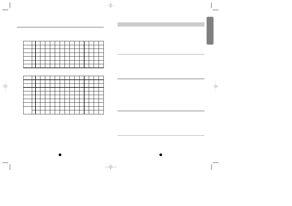
Preset Mode Table
The timing shown in the following table will be factory preset for display.
Display modes memory
User setting area
Factory presetting area
Automatic save
Horizontal
Frequency
Period(T1)
Sync Width(T2)
Back Porch(T3)
Active(T4)
Front Porch(T5)
Pixel 640
31.469
31.778
2.542
3.178
25.422
0.635
720
31.469
31.778
3.813
1.907
25.422
0.636
640
31.469
31.778
3.813
1.907
25.422
0.636
640
37.500
26.667
2.032
3.810
20.317
0.508
640
37.861
26.413
1.270
3.810
20.317
0.762
640
35.000
28.571
2.116
3.175
21.164
2.116
800
35.156
28.444
2.000
3.555
22.222
0.667
800
37.879
26.400
3.200
2.200
20.000
1.000
800
46.875
21.333
1.616
3.232
16.162
0.323
800
48.077
20.800
2.400
1.280
16.000
1.120
1024
48.363
20.677
2.092
2.462
15.754
0.369
1024
56.476
17.707
1.813
1.920
13.653
0.320
1024
60.023
16.660
1.219
2.235
13.003
0.203
1024
57.928
17.247
1.662
2.078
13.299
0.208
KH
2
µs
µs
µs
µs
µs
Vertical
Frequency
Period(T1)
Sync Width(T2)
Back Porch(T3)
Active(T4)
Front Porch(T5)
Line 350
70.087
14.268
0.095
1.905
11.136
1.145
400
70.087
14.268
0.064
1.080
12.711
0.413
480
59.940
16.683
0.064
1.048
15.253
0.318
480
75.000
13.333
0.080
0.427
12.800
0.027
480
72.809
13.735
0.079
0.528
12.678
0.238
480
66.667
15.000
0.086
1.110
13.714
0.086
600
56.250
17.778
0.057
0.626
17.067
0.028
600
60.317
16.579
0.106
0.607
15.840
0.026
600
75.000
13.333
0.064
0.448
12.800
0.021
600
72.188
13.853
0.125
0.478
12.480
0.021
768
60.004
16.666
0.124
0.600
15.880
0.062
768
70.069
14.272
0.106
0.513
13.599
0.053
768
75.029
13.328
0.050
0.466
12.795
0.017
768
72.117
13.866
0.121
0.448
13.246
0.086
H
2
ms
ms
ms
ms
ms
Interlaced
N
N
N
N
N
N
N
N
N
N
N
N
N
N
Y/N
Sync Polarity
P
N
-
-
-
-
-
-
-
-
-
-
-
-
H
N
P
-
-
-
-
-
-
-
-
-
-
-
-
V
English
*1¿
97.3.29 10:26 AM ˘
`
12