Insinger Commander 18-6 User Manual
Page 11
INSTALLATION INSTRUCTIONS
Commander 18-6 Series & CS Series
PART 2 INSTALLATION INSTRUCTIONS
DoorTypeTM2013
www.insingermachine.com 800-344-4802
Placement
Carefully uncrate machine. Take caution not to damage
components which may be mounted on the top or
sides of the machine. Set unit in place and adjust the
feet to level the machine.
Fasten the tables to the load and unload side of the
machine. Most installations require fastening the
turn-down lip of the dish tables to the side of the
machine with flathead countersunk screws. The table
design should provide horizontal clearance of 30” for
servicing.
Electrical Connections
Connect electrical lines sized for the correct voltage,
current and phase of the machine. These should
agree with the machine requirements indicated on the
nameplate and labels on the control panel.
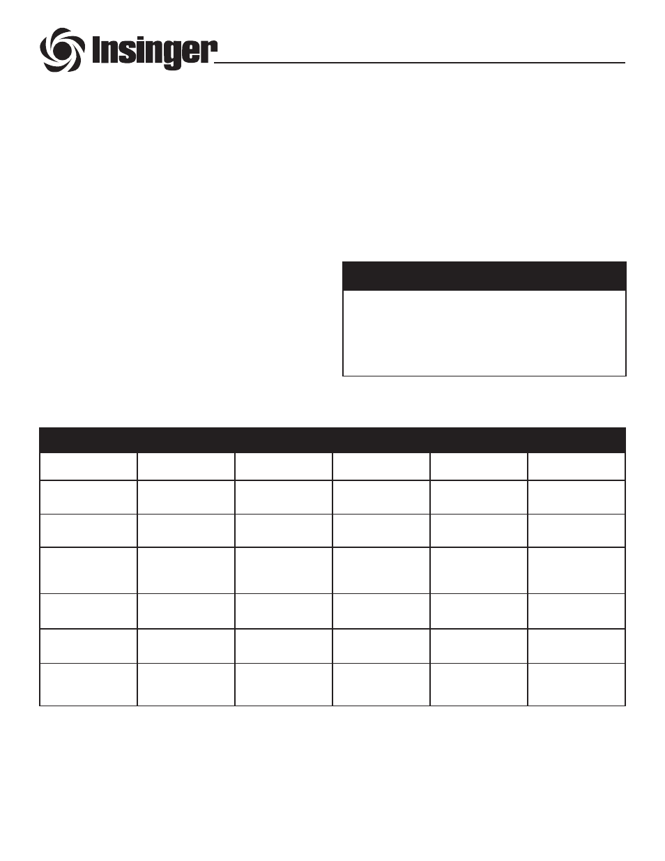
CAUTION:
Connections must be made to a circuit breaker
or fused disconnect as provided by the end-user
and required by local codes.
A laminated wiring diagram is inside the control panel.
9
A single-point electrical connection is provided for the
pumps, control circuit, and wash tank heater.
If an electric booster is provided, connect power
directly to the booster.
If the Insinger Self-Contained booster is provided
the machine comes standard with a Single-Point
Connection (to include the booster).
Fuse Sizing Chart
Model
208VAC/3PH
240VAC/3PH
380VAC/3PH
480VAC/3PH
220VAC/1PH
18-6 (C)
Steam heat
10A
10A
6A
6A
15A
18-6 (C)
Electric heat
20A
20A
10A
10A
35A
18-6 (C)
Electric heat
Insinger SCB
60A
50A
30A
25A
90A
18-6H (C)
Steam heat
10A
10A
10A
6A
20A
18-6H (C)
Electric heat
25A
25A
15A
15A
40A
18-6H (C)
Electric heat
Insinger SCB
60A
60A
35A
30A
100A
®