Typical installation – InSinkErator LC-50 User Manual
Page 4
Advertising
4
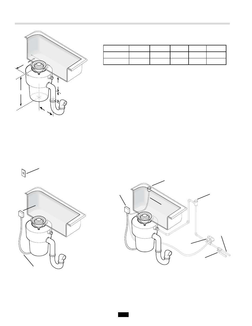
Wall Switch
Electric Supply
Push Button
Syphon Breaker
Solenoid Valve
Water Shutoff Valve
Cold Water
Supply
Electrical
Junction Box
Air Hose
Air Switch
Power Junction
OPTIONAL
DIRECT WATER
CONNECTION
D
E
A
C*
B*
Dimension
A
B*
C*
D
E
Inches
14-9/16
6-13/16
4
8
5-3/4
Cm
37.0
17.3
10.2
20.3
14.6
B* – Distance from bottom of sink to center line of disposer outlet.
Add 1/2" (13mm) when stainless steel sinks are used.
C* – Length of discharge tube from center line of disposer outlet to
end of discharge tube.
Important – Plumb waste line to prevent standing water in
disposer motor housing.
Typical Installation
INSTALLATION WITH WALL SWITCH
INSTALLATION WITH REMOTE AIR
SWITCH AND OPTIONAL DIRECT
WATER CONNECTION
Advertising