0 connection – Interlink Electronics 4-Zone FSR Mouse Sensor User Manual
Page 8
www.interlinkelectronics.com
6
4-Zone Mouse Sensor
Integration Guide
Heat generated during the soldering of components can damage the FSR. Therefore, the sensor
should not be mounted until PCB assembly is complete. When laminating the FSR to the PCB, be
sure to use a hard roller or other depression tool to ensure proper bonding of the sensor’s
pressure-sensitive adhesive and the removal of any air bubbles.
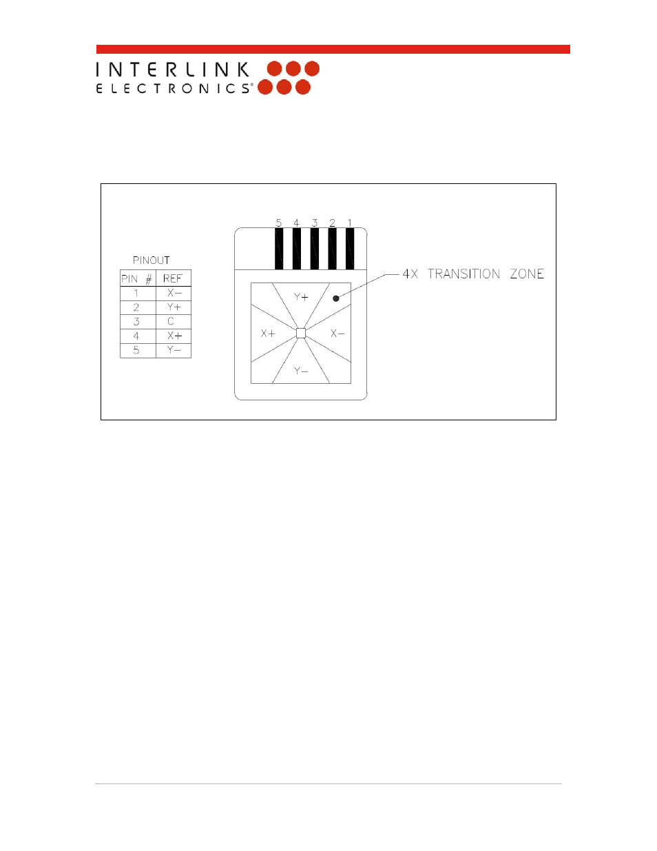
Figure 5: 4-zone FSR pinout reference. Sensor is shown with silver contacts facing away.
5.0 Connection
The 4-zone FSR is connected to the PCB with either a pressure-sensitive z-axis conductive
adhesive or a heat-bonded z-axis conductive adhesive. Both methods of adhesion are meant to
provide an electrical, not mechanical bond; therefore, a mechanical means of applying constant
pressure to the joint should be incorporated into the mounting of the 4-zone FSR. This will
prevent the delamination of the adhesive, which can lead to an open circuit and failure of the
module.
Recommended Conductive Adhesives:
3M 9703/9705 Anisotropic Electrically Conductive Adhesive Transfer Tape
3M 7303 Heat-Bondable Anisotropic Electrically Conductive Adhesive Film