Connections, controls, and indicators – LD Systems XS 700 User Manual
Page 10
ConnECtionS,
CONTROLS, AND INDICATORS:
15
GAIN
Adjustment of the input sensitivity and/or voltage gain of the power amplifier. When this switch is in the
middle position, all 3 power amplifiers in this series have a voltage gain of 26 dB. For the other values,
please see the specifications in the chapter "Specifications".
16
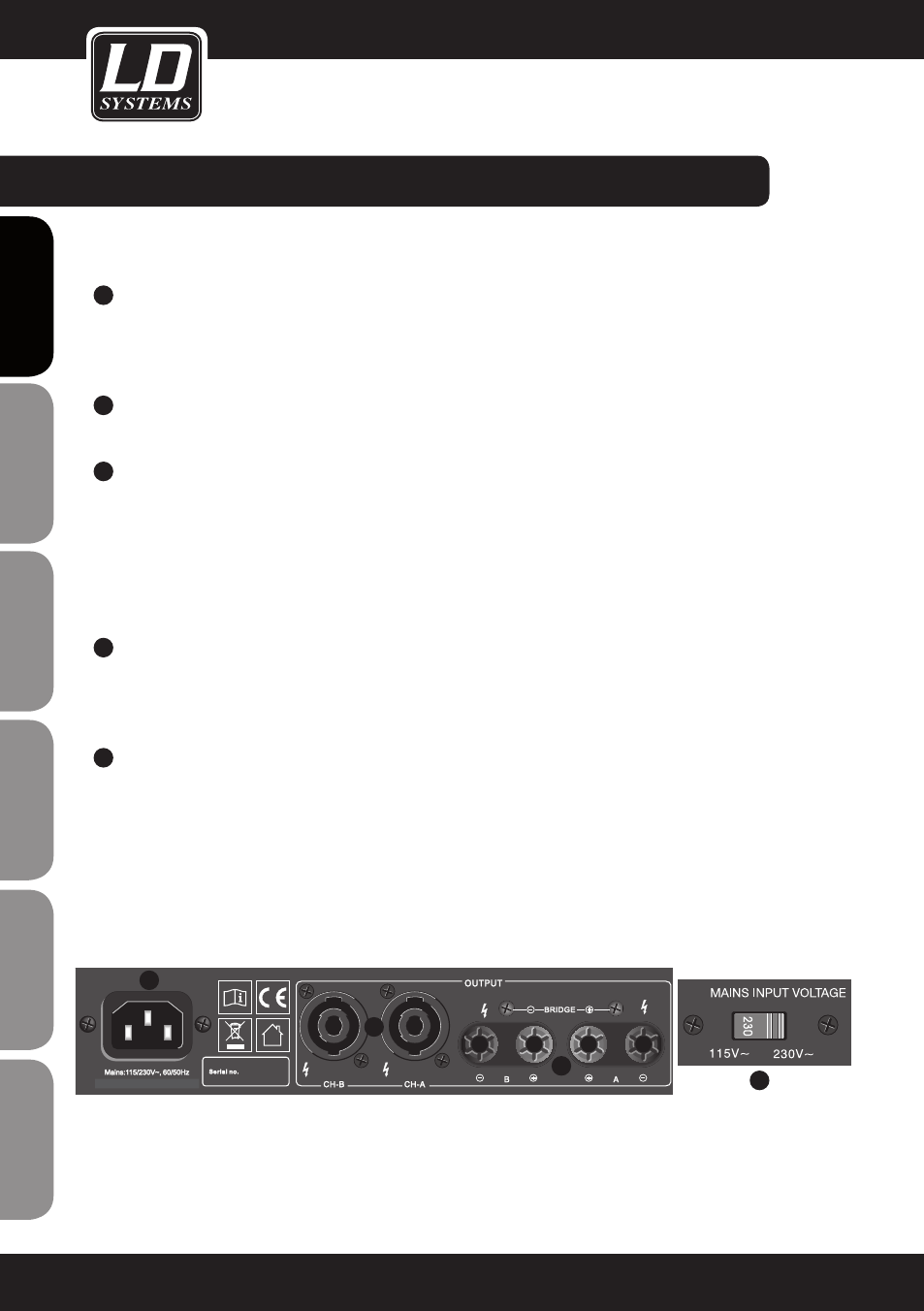
OUTPUT CH-A / CH-B (SPEAKON-COMPATIBLE SOCKETS)
Connection of speakers or speaker systems with a total impedance of at least 4 ohms per channel.
17
SPEAKER TERMINAL CLAMPS CH-A / CH-B
Connection of speakers or speaker systems with a total impedance of at least 4 ohms per channel. Connect
the positive pole (+) of the speaker cable to the red terminal clamp (+) and the negative pole (-) of the
speaker cable to the black terminal clamp (-) of the respective channel.
In
bridge mode, the red Channel A terminal clamp must used as the positive pole (+) and the red Channel B
terminal clamp must be used as the negative pole (-).
IMPORTANT: In bridge mode, the total impedance of the connected speaker system must not be less than 8 ohms.
18
IEC POWER SOCKET
IMPORTANT INFORMATION: Make certain BEFORE start-up that the switch (19) for the operating voltage
(115V~ or 230V~) on the underside of the housing is in the correct position! The mains voltage of your
energy supplier and the operating voltage of the power amplifier must match!
19
MAINS INPUT VOLTAGE 115V~ / 230V~
Switch for setting the operating voltage. The mains voltage of your energy supplier and the operating voltage
of the power amplifier must match!
10
ENGLISH
DEUTSCH
FRANCAIS
FRANCAIS
FRANCAIS
FRANCAIS
FRANCAIS
ES
pA
ño
L
po
LSKI
IT
ALIAN
o
X S 2 00
X S 4 00
X S 7 00
16
17
18
19