Connections, controls, and indicators – LD Systems XS 700 User Manual
Page 9
9
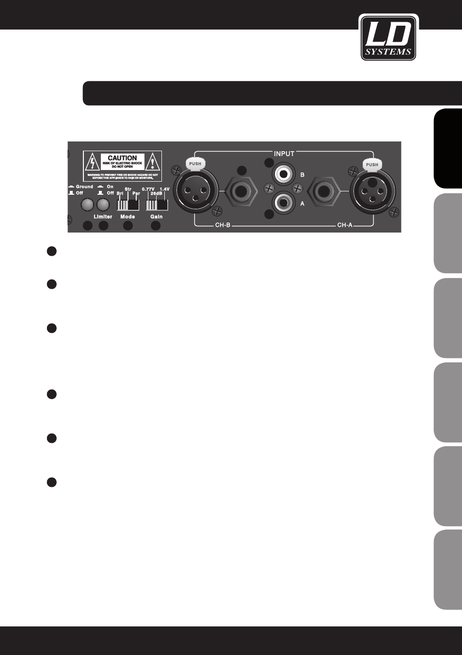
INPUT CH-A / CH-B (XLR)
Balanced XLR line inputs Channel A and B.
10
INPUT CH-A / CH-B (6.3 MM JACK)
Balanced jack inputs Channel A and B.
11
INPUT CH-A / CH-B (RCA)
Unbalanced RCA inputs Channel A and B.
The line inputs are used to connect to a mixing desk or another signal source. In bridge mode, Chan-
nel A must be used as the input.
12
GROUND OFF / ON
This function (when the switch is not depressed) can eliminate ground loop hum if devices with a different
ground potential are connected.
13
LIMITER
Switchable clip limiter. When the switch is depressed, the integral clip limiter is activated, which limits the
power amplifier output to the maximum possible output level.
14
MODE
STEREO MODE (STR): In stereo mode, power amplifier channels A and B operate independently. Both stereo
signals and entirely different signals can be amplified via Channel A and B.
PARALLEL MODE (PAR): One line input (INPUT A or B) supplies the same signal to both power amplifier
channels A and B.
BRIDGE MODE (BRI): In bridge mode, output stages A and B are connected to a more powerful mono output stage.
Channel A is used as a line input, the volume is adjusted using the Channel A volume control, and the terminal
clamps (red Channel A terminal clamp as positive pole (+) and red terminal clamp Channel B as negative pole
(-)) are used as the power amplifier output.
IMPORTANT: In bridge mode, the total impedance of the connected speaker system must not be less than 8 ohms.
ConnECtionS,
CONTROLS, AND INDICATORS:
9
IT
ALIANO
POLSKI
ESP
AÑOL
FRANCAIS
FRANCAIS
FRANCAIS
FRANCAIS
FRANCAIS
DEUTSCH
ENGLISH
X S 2 00
X S 4 00
X S 7 00
9
11
12 13
14
15
10
11