Leprecon W-DMX G4 MK I User Manual
Page 7
4 BlackBox and WhiteBox F-1
12
W-DMX G4(S) User Manual, edition 2
2013-10
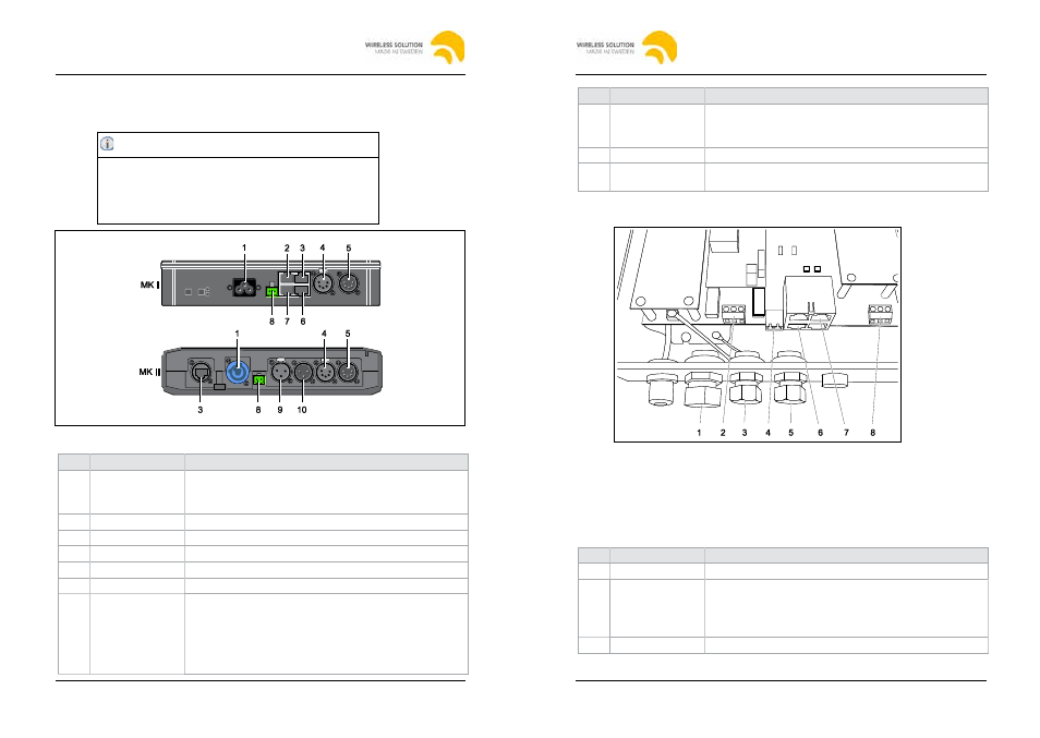
4.2
Connectors and ports
4.2.1
BlackBox F-1
Caution
Damage to the unit!
Connecting more than one DMX Universe at a time
damages the unit.
• Connect only one DMX Universe input at a time.
Fig. 2: Connectors and ports of F-1
No. Port
Description
1
AC power input
U
AC
= 90–250 V / 50–440 Hz
MK I: IEC 2.5A connector
MK II: PowerCon 20A connector
2
Reserved
–
3
Ethernet (optional) RJ 45 port (MK II: EtherCon RJ 45 port)
4
DMX OUT bypass XLR female 5 pin Universe 1
5
DMX IN
XLR male 5 pin Universe 1
6
Reserved
–
7
DMX IN / OUT
RJ 45 port (not BlackBox MK II):
1: Universe 1+
5: –
2: Universe 1-
6: –
3: –
7: Universe 1 GND
4: –
8: –
4 BlackBox and WhiteBox F-1
2013-10
W-DMX G4(S) User Manual, edition 2
13
No. Port
Description
8
DC power input
Input for Phoenix gold connector:
• Left: Ground
• Right: U
DC
= +12 V
9
DMX OUT bypass XLR female 3 pin (BlackBox MK II only)
10
DMX IN for
Universe 1
XLR male 3 pin output for Universe 1 (BlackBox MK II only)
4.2.2
WhiteBox F-1 MK I
Fig. 3: Connectors and ports of the WhiteBox F-1 MK I
To ensure safe transmission of signals for outdoor use, the WhiteBox does not
have XLR connectors. For this reason the connection of DMX signal cables
differs slightly from the BlackBox models, which are for indoor use only.
To install the unit it is necessary to open the housing. See
chapter "4.4.2 WhiteBox F-1", page 17.
No. Port
Description
1
Cord Strip
For AC power input (2)
2
AC power input
U
AC
= 90–250 V / 50–440 Hz:
• Left: Outer conductor (L)
• Middle: Ground (GND)
• Right: Neutral conductor (N)
3
Cord Strip
For DC power input (4)
2014-03
W-DMX G4(S) User Manual, edition 3
2014-03
W-DMX G4(S) User Manual, edition 3