Leprecon W-DMX G4 MK I User Manual
Page 9
4 BlackBox and WhiteBox F-1
16
W-DMX G4(S) User Manual, edition 2
2013-10
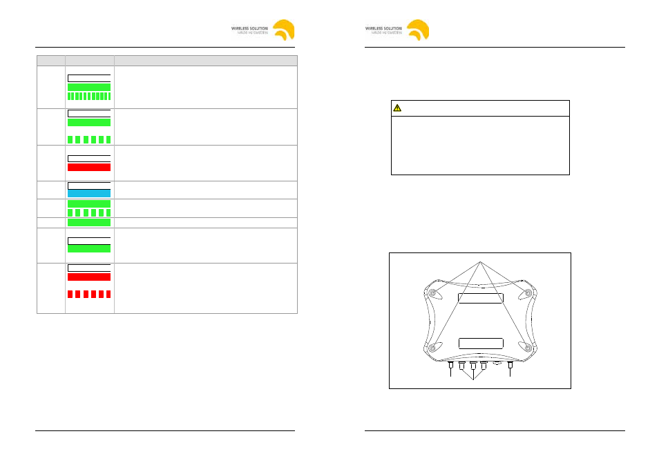
Name LED signal
Description
RX mode:
• Off: Unit is not linked to any transmitter.
• On: Unit is linked to transmitter.
• Rapid Flashing: Transmitters are being searched or
linked transmitter is lost.
G4
• Off: Unit is in G3 mode.
• On: Unit is in G4 or G4S 2.4 GHz mode.
G4/G4S is indicated by red SIGNAL LED on the unit.
• Flashing: Unit in G4S 5.8 GHz mode
1
SIGNAL
TX mode:
• Off: Unit is in G4S mode.
• On: Unit is in G4 mode.
RX mode: Part of signal strength
PWR
Power on / off
RX
• On: Unit is in RX (receiver) mode.
• Flashing: Receiver is in repeater mode.
DATA
Data is available at the input / output.
RDM
WhiteBox: included, BlackBox: optional
• Off: No RDM data is available on output.
• On: RDM data is available on output (RDM Downstream
activated).
CTRL
• Off: Normal operation.
• On: Switch between normal operation (CTRL LED off)
and CTRL mode (flashing).
• Flashing: CTRL mode is active
To set the frequency band, see chapter "4.8 Switching
CTRL modes", page 23.
1
5.8GHz is not available in all countries. For more info please contact
Wireless Solution (see page 2).
4.4
Installing the unit
4.4.1
BlackBox F-1
1. Choose one of the following options to make the DMX connection:
– Connect the DMX source to the XLR 5 pin DMX IN port, XLR 3 pin DMX
IN port (BlackBox MK II only) or to the RJ 45 DMX IN port (BlackBox
MK I only).
– Connect the DMX fixture to the XLR 5 pin DMX OUT port, XLR 3 pin
OUT port (BlackBox MK II only) or the RJ 45 DMX OUT port (BlackBox
MK I only).
4 BlackBox and WhiteBox F-1
2013-10
W-DMX G4(S) User Manual, edition 2
17
– Unit with optional Ethernet lighting protocol support:
Connect the Ethernet lighting source or output to the Ethernet in port.
2. Attach the supplied standard antenna(s) and standard adapter(s) or other
suitable antenna(s) / adapter(s) available from Wireless Solution to the
matching connector(s).
Warning
Risk of death by electrocution!
AC power connection must be carried out correctly.
• Make sure that only a qualified and trained electrician
carries out AC power connection.
• Make sure the correct Schuko connector or other
connector suitable for your country is used.
3. Choose one of the following options to connect the power to the unit:
– Attach a suitable mains plug to the supplied power cord and connect the
power supply to the AC power input.
– Connect the power supply to the DC power input.
4. If required, attach the unit to the supplied mounting brackets or other
mounting hardware available from Wireless Solution.
4.4.2
WhiteBox F-1
1
3
2
4
Fig. 6: Housing of the WhiteBox models
2014-03
W-DMX G4(S) User Manual, edition 3
2014-03
W-DMX G4(S) User Manual, edition 3