Installation and operating instructions – Louroe Electronics TLMC-W User Manual
Page 2
MICROPHONE AND SPEAKER WIRING CONNECTIONS
Microphone Portion
1) Connect cable to TLMC-W as shown in the wiring diagram page 3.
2) Connect microphone wires (2 cond. shielded) to terminal block of PC board
marked “A”, “B” and “C”. If using West Penn 356:
a. Connect RED wire to terminal marked “A”.
(12Vdc power)
b. Connect BLACK wire to terminal marked “B”.
(Audio Output)
c. Connect DRAIN (bare) wire to terminal marked “C”.
(Ground)
Speaker Portion
3) Connect speaker wires (2 cond. unshielded) to terminal block
marked “SP”, “6”, or “7”. Again If using West Penn 356:
a. Connect GREEN wire to terminal marked “SP”.
(speaker positive)
b. Connect WHITE wire to terminal marked “7”. (70V)
(speaker return)
NOTE: Terminal “6” is not used with this application.
4) Connect other end of 4 conductor cable to the corresponding
terminal blocks of the Louroe alarming base station. Refer to the
instructions for the specific base station being used.
NOTE: If using wiring from other manufacturers, color code may vary.
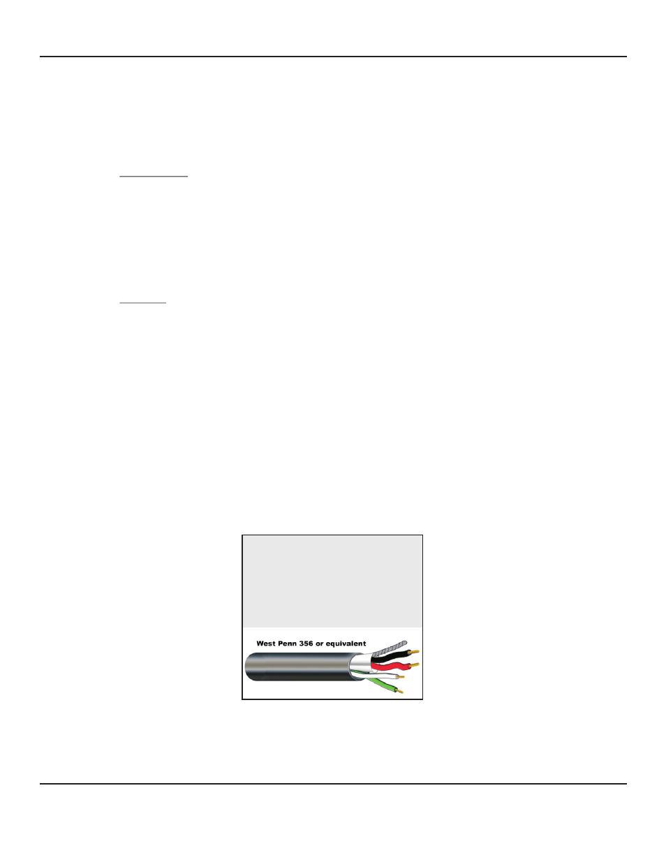
WIRING REQUIREMENTS
4 Conductor consisting of:
+ 2 Conductor shielded, 20 gauge
with 22 gauge drain (microphone
connection)
+ 2 Conductor unshielded, 18 gauge
(speaker connection)
All in the same jacket
Page 2 of 8
LOUROE ELECTRONICS 6 9 5 5 VA L J E A N AVENUE, VAN NUYS, CA 91406
TEL (818) 994-6498
FAX
994-6458
website: www.louroe.com e-mail: [email protected]
(818)
®
INSTALLATION AND OPERATING INSTRUCTIONS
tlmc_w_inst_3/15