Installation and operating instructions c, Model dcs – Louroe Electronics DCS-1 User Manual
Page 2
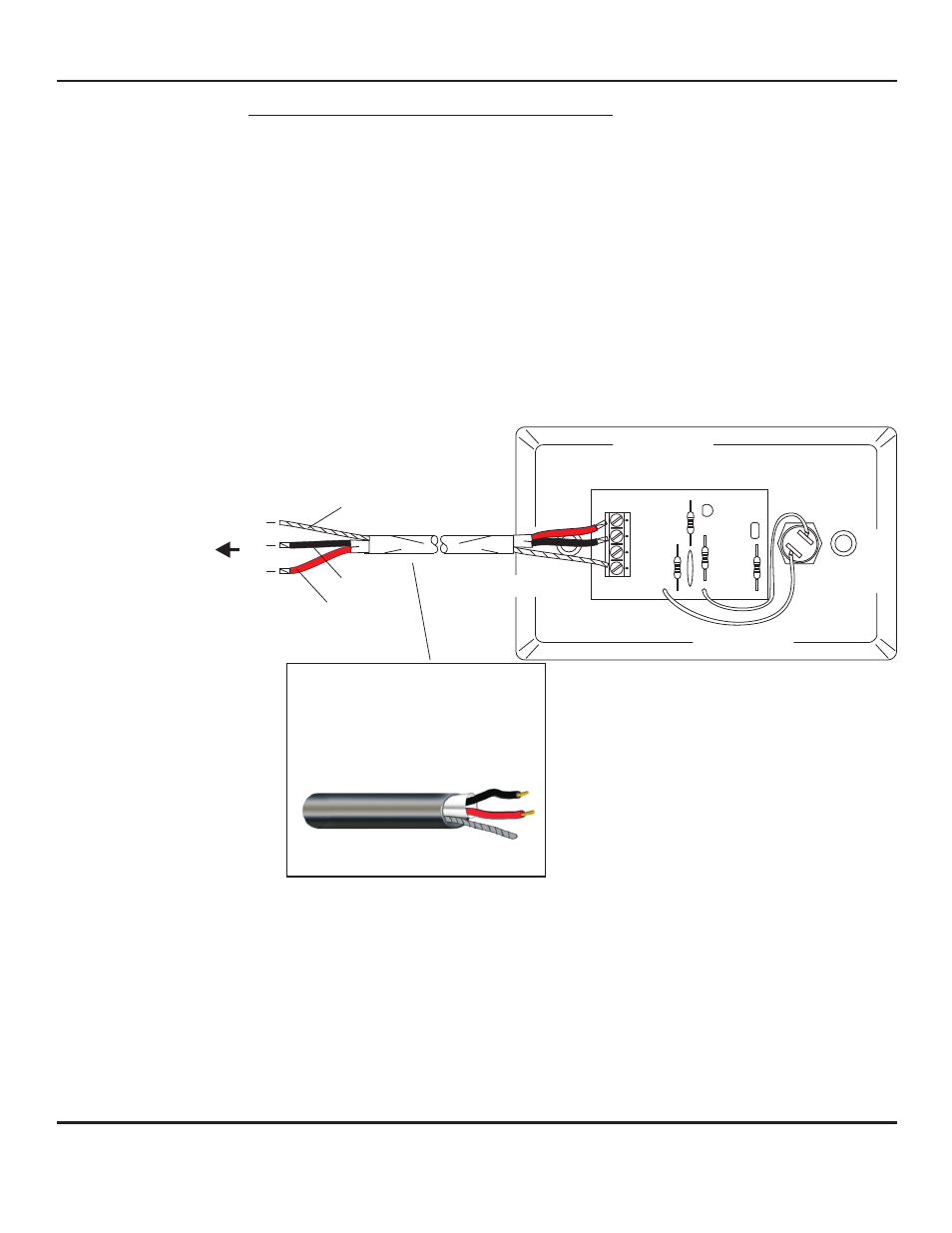
The PC board of DCS-1 contains a barrier block with four terminals marked 1, 2, 3 and 4.
1 - Ground or common
2 - Jumper (installed by factory). This terminal not used with DCS-1
3 - Output of Oscillator
4 - +12Vdc Power
WIRING CONNECTION TO DCS-1 DURESS CALL STATION
CONNECTION TO MODEL DG-12II OR DG-25III ALARMING BASE STATION
Located on rear panel are 12 or 25 sets of 5-pin headers marked A, B, C, SP and G. Connect:
Red wire to pin A
Black wire to pin B
Bare wire to pin C
Pins SP and G are not used with this application
Refer to installation/operation instructions of ALA-4/ALA-8 and
DG-12II/DG-25III for additional information
WIRE COLOR CODE OF WEST PENN 452
- 12Vdc
BLACK
- Audio Output
- Ground
If using wiring from other manufacturers,
color code may vary.
RED
BARE
Page 2 of 4
LOUROE ELECTRONICS 6 9 5 5 VA L J E A N AVENUE, VAN NUYS, CA 91406
TEL (818) 994-6498
FAX
994-6458
website: www.louroe.com e-mail: [email protected]
(818)
®
INSTALLATION AND OPERATING INSTRUCTIONS
C
2
B
3
A
4
TO TERMINAL BLOCK OF
LOUROE DG SERIES BASE
STATION
REFER TO THE SPECIFIC BASE
STATION
INSTALLATION INSTRUCTIONS
FOR PROPER
CONNECTIONS
MODEL DCS
BLACK
BLACK
BARE
BARE
RED
RED
2 Conductor shielded cable, 22
gauge with a 24 gauge drain wire
NOTE:
Unshielded cable is not
satisfactory for audio systems
WIRING REQUIREMENTS
West Penn 452 or equivalent
1
dcs-1_inst_3/15