3 dimmer operation, 1 control panel, 2 setting the dmx512 address – LSC Lighting ePRO User Manual
Page 6: Dimmer operation, 3dimmer operation
ePRO Dimmer
Operator Manual V3.0
3
3
DIMMER OPERATION
3.1 Control Panel
The control panel on the ePRO dimmer is
designed to be concise and easy to operate. It
allows quick access to all functions and provides
indicators that show the exact status of the
dimmer.
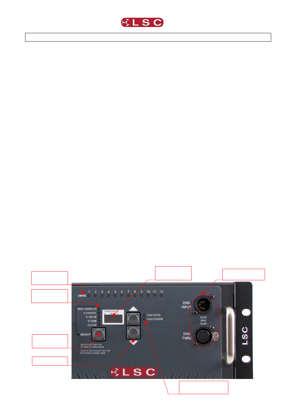
The control panel is shown below. The following
is a brief explanation of the buttons and displays.
Channel Drive LEDs: These LED’s indicate the
channel output status and will glow
proportionately to the level of output being
generated. In SCENE mode, these LEDs are
used to build the desired output levels for the
scene to be stored. When the scene is recalled
these LEDs will correspond to the output levels
stored in memory.
Mode Select Button: This button is used to alter
the dimmer’s status by allowing the operator to
set the DMX512 address, drive individual channel
at varying levels, create a scene to be stored in
memory and individually set different dimmer
curves for each channel (ePRO only).
Mode Status Indicators:
These
LEDs
indicate which mode the dimmer is operating in.
Scroll Buttons:
These up and down
buttons allow the operator to adjust the DMX512
address, channel number and channel output
level, in either a up (increment) or down
(decrement) direction.
Status Display:
The 3 digit display can indicate
the current DMX512 address, channel number
and the channel output level. The output of the
display is dependent on which mode the dimmer
is currently in. Under other conditions the display
will also scroll prompt and error messages.
DMX Data Indicators: These two LEDs indicate
good or bad data being received by the dimmer.
3.2 Setting the DMX512 Address
The dimmer is designed to be controlled by an
external DMX512 transmitting device. The
DMX512 protocol allows for the high speed
transmission of 512 channels of digital data and
allows for up to 32 devices to be connected to
each DMX512 stream. To enable each device to
receive its own relevant information off this
DMX512 stream, a DMX512 Start Address is
allocated to each dimmer.
When the dimmer is powered up for the first time,
it will automatically be in the DMX512 Address
mode and display channel 1 as its starting
address. The user can then set the desired start
address by pressing the increment (
) or
decrement (
) Scroll Buttons. If you decrement
from channel 1, the next setting will be 512. To
scroll quickly to your desired start address, press
and hold the increment or decrement button. The
display will then speed up and scrolls through the
channel numbers.
To increase the start address in banks (groups of
12 for 12 channel dimmers and groups of 6 for 6
channel dimmers), press the increment button
quickly once and then press and hold. If the
dimmer start address is currently “001”, then to
select the next bank (start address number 13/7),
press the increment button quickly once and then
press again and hold. The display will then
Channel
Drive LEDs
Mode status
indicators
Mode select
button
Status Display
Scroll buttons
DMX Data Indicators
DMX connectors