LSC Lighting iSeries User Manual
Page 11
V1.21 September 2007
iPAK/iPRO Dimmer Operator Manual
LSC Lighting Systems (Aust) Pty Ltd
7
3.4
Overload Protection
Each dimmer is fitted with twelve (six) fast acting Miniature Circuit Breakers (MCB’s),
one for every output channel. Under normal operating conditions the MCB’s pass the
rated current and will only trip when there is an overload through the dimmer circuit.
Likewise, if there is a short circuit on the load or faulty wiring on the load side, the MCB
will trip to protect the internal components of the dimmer.
The MCB’s are located on the front panel of the dimmer allowing quick visual access
to which channel has a fault or overload condition. Dimmer channels can be manually
disabled by switching off the MCB for that particular channel. This is particularly useful
for those occasions where a genuine fault has occurred.
3.5
Installing the Dimmer
The iPAK and iPRO dimmers are one of the most versatile dimmers on the market,
offering no less than four different installation options. The dimmers can be floor or
bench mounted; hung from lighting bars or handrails; mounted to walls; or fastened to
19” rack systems.
The angled bottom of the Installation Frame allows
the dimmer to sit angled on a floor, bench or table
top. This is ideal for portable situations where the
dimmer can be placed in awkward positions to
allow easy interconnection to the load circuits. In
this scenario we recommend great care is taken so
power and data leads and the connecting load
circuits do not create an operational hazard to
others.
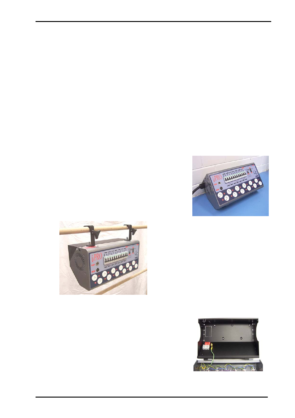
On the top of the Dimmer Chassis, three 12mm
holes are provided for the attachment of two 2”
Hook (C) clamps and a safety chain. The holes
are positioned to allow the centre of gravity of
the dimmer to be directly underneath. To fit the
Hook clamps, the two screws holding the
Dimmer Chassis to the Installation Frame need
to be removed and the Dimmer Chassis hinged
forward. From the inside fit two bolts to fasten
the Hook clamps to the top of the Dimmer
Chassis. There are two holes, one on the top
left and one on the upper side left of the
Chassis, that allow the connection of a rated
safety chain.
The rear panel of the dimmer has provisions for
mounting to walls and other upright structures. In
this situation care must be taken not to mount the
dimmer close to other dimmers or objects, such
that the side air vents of the dimmer may be
impeded. Allow a minimum of 150mm clearance on
either side of the dimmer. The eight holes on the
outer side of the rear chassis allows the dimmer to
be fastened to a 19” rack frame.