Caution – Mathey Dearman 1SA Saddle Machine User Manual
Page 6
6
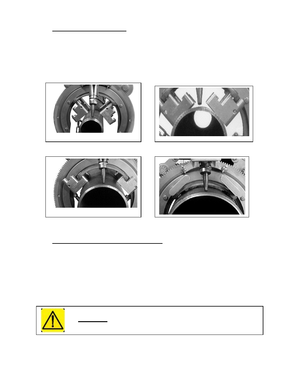
4.0 Installation Step Spacer
4.1 For 3”, 4” and 6” pipe place the spacer bolt through the hole in the top of the saddle and tighten into
the step spacer as shown in the pictures below.
4.2
For 8” pipe place the step spacer bolt on top side of the saddle with the flat side facing outward.
Align the hole in the center of the step spacer with the hole on the top side of the saddle. Insert the
spacer bolt through the hole in the bottom side of the saddle and tighten.
4.3 If the is necessary to securely tighten the step spacer a coin can be place in the half moon slot on top
of the spacer bolt.
3” Pipe
4” Pipe
6” Pipe
8” Pipe
Picture 3 – Step Spacer Installation
5.0 Installation of 1SA Machine on Pipe
5.1
Place the 1SA Saddle Machine squarely on the pipe, as close as possible to the cut line. All 4 spacer
bolts or step spacers should contact the pipe.
5.2
Place the hook of the Boomer (Figure 3 item 1) into the Boomer Eye (Figure 5 Item 7) on the Saddle
(Figure 5 Item 1).
5.3
Place the Spring Snap (Figure 3 Item 4) into the Boomer Eye (Figure 5Item 7) on the other side of the
Saddle (Figure 5 Item 1).
5.4
In order to get a stable installation of the Saddle Machine, the Chain (Figure 3 item 3) of the Boomer
Assembly must be adjusted on the Spring Snap (Figure 3 Item 4) so that the spring is stretched
approximately 1/2" -3/4” (12 - 19mm) when the Boomer is closed.
5.5
When the Chain is properly adjusted, close the Boomer (Figure 3 item 1).
Caution:
Improper tensioning of the boomer assembly or failure to latch the
boomer assembly may result in injury.