Caution, 0 the cutting process – Mathey Dearman 1SA Saddle Machine User Manual
Page 9
9
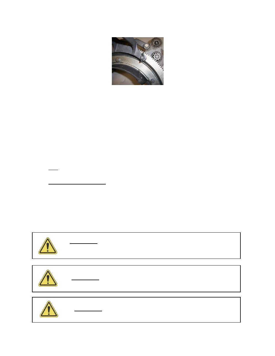
Picture 6 – Installation of the wing Nut
6.2
Remove the Clamp from the (Figure 4 Item 3) from the torch Carrier Assembly (Figure 4 Item B).
6.3
Place the Torch Carrier Assembly (Figure 4 item B) on the Torch Arm (Figure 4 item A) with hole for Torch of
the Torch Clamp (Figure 4 Item 2) nearest the ring gear.
NOTE: For the squarest cut place the torch as close to the Ring Gear (Figure 4 item 3) as possible.
6.4
Reinsert Thumbscrew (Figure 4 Item 6) through the hole in the base of the clamp base (Figure 4 item 1) and
thread it into the Clamp (Figure 4 item 3) securing the Torch Carrier Assembly to the Torch Arm.
6.5
The Torch Clamp Base (Fig. 4 Item 1) is marked 0, 60, and 90. Use “0” Position for square cuts (no bevel).
Positions 60 and 90 make the appropriate bevel to produce a “V” Groove of 60 and 90 degrees respectively when
the two pipe ends are butted together.
6.6
Select the correct Cutting tip for the wall thickness and fuel gas per the torch manufactures instructions.
6.7
Insert 10” Long 1 3/8” diameter Machine Oxy/fuel or Plasma Machine Torch (not supplied) into Torch Clamp
(Fig. 3, Item 2) and adjust torch tip to pipe height per the torch manufacturer instructions and tighten the
Thumbscrew (Fig. 3, item 6) securing the Torch in the Torch Carrier Assembly.
Note: A 10” long Oxy/fuel or Plasma machine torch is required for the 1SA Saddle Machine to cut all pipes within its
range.
7.0 The Cutting Process
7.1
Rotate Torch one full turn around the pipe to be sure torch tip will maintain the same distance around the pipe.
Note: If the torch tip contacts the pipe at any point during its rotation either the incorrect spacer bolts were
selected or the pipe is oversize or out of round. If the distance of the torch tip is greater at the 6:00 o’clock
either the incorrect spacer bolts were selected or the pipe is undersize or out of round.
7.2
Connect the gas hose from the fuel regulator to the left hand thread port 10” long Oxy/fuel or Plasma Machine
Torch per the manufacturer’s instructions.
7.3
Connect the oxygen hose from the oxygen regulator to the right hand thread port 10” long Oxy/fuel or Plasma
Machine Torch per the manufacturer’s instructions.
Caution:
T
he hose must not be drawn through the molten slag produced by the
cutting process
Caution:
T
he oxygen and fuel hoses must be connected to the right port on the
machine torch. Failure to do so may result in serious injury.
Caution:
Goggles, gloves, mask and other appropriate safety attire must be worn
during the cutting process.