0 installation of saddle machine on pipe, Caution – Mathey Dearman 4SA Saddle Machine User Manual
Page 5
5
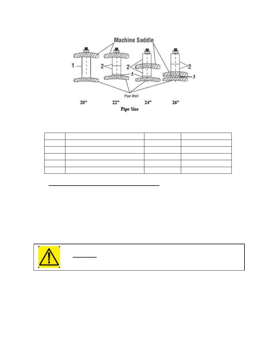
Figure 1: Spacer Configuration for 20”, 22”, 24”, & 26” pipe
Table 1 – Spacer Bolt Part Identification
4.0 Installation of Saddle Machine on Pipe
4.1
Place the Saddle Machine squarely on the pipe, as close as possible to the cut line. All 4 spacer bolts
should contact the pipe.
4.2
Place the hook of the Boomer (Figure 2 item 1) into the Boomer Eye (Figure 4 Item 8) on the Saddle
(Figure 4 Item 1).
4.3
Place the Spring Snap (Figure 2 Item 4) into the Boomer Eye (Figure 4 Item 8) on the other side of the
Saddle (Figure 4 Item 1).
4.4
In order to get a stable installation of the Saddle Machine, the Spring Snap (Figure 2 Item 4) of the
Boomer Assembly (Figure 2) must be adjusted on the Chain (Figure 2 item 3) so that the spring
(Figure 2 Item 2) is stretched approximately 1/2" -3/4” (12 - 19mm) when the Boomer is closed.
4.5
When the Chain is properly adjusted, close the Boomer (Figure 2 item 1).
ITEM #
PART DESCRIPTION
PART #
QUANTITY REQUIRED
1
Spacer Bolt for 20” / 508mm pipe
03-0110-008
4
2
Spacer Bolt 20” pipe
03-0110-011
4
3
Spacer 1” / 25.4mm
04-0106-018
8
4
Hex Nut, 1/2 - 13
1H-12C0-000
4
5
Spacer Bolt Kit (includes all of the above)
03-04SA-KIT
1
Caution:
Improper tensioning of the boomer assembly or failure to latch the boomer
assembly may result in injury.