Parts list, Preparations, Two mounting methods – Maytag MMC5080AAB Installation User Manual
Page 2: Template 1 • template 2, Template cut lines cabinet front
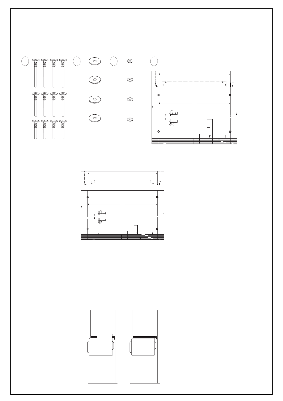
PARTS LIST
1. 3 Sets of bolts
2. 4-washers-A
3. 4-washers-B
4. 1-Template
Upon completing your check of the parts list, read all instructions completely before starting the installation. This will help you to become
familiar with the process and make installation easier.
(NOTE: It is suggested that you gather all needed tools and installation parts in one location.)
PREPARATIONS
Open the template and detach both segments along the dashed line with scissors. You should have two separate pieces.
•
Template 1
•
Template 2
TWO MOUNTING METHODS
There are two mounting methods described in this booklet that can be used.
1.
Countertop Method
You can use this method if you decide not to cabinet mount your oven.
To use your oven as a countertop model, simply position the oven on the desired counter and plug the electrical cord into a three
prong (grounded)wall receptacle.
2.
Cabinet Mounting Method
This method is for mounting your oven under a cabinet and uses the template, 4-washers and one set of screws. Before using this method,
the 4 plastic plug buttons on the top of the oven must be removed. This can be done by placing a thin flat blade screwdriver between the
plug button and the oven top and raising gently, taking care to avoid acratching the oven top.
OVEN MAY BE MOUNTED TO CABINETS WITH OR WITHOUT A FRONT RAIL.
If you drill the 4 mounting holes from the inside of the cabinet - place the
front edge of the template at the front edge of the cabinet.
Drill the 4 holes 1/4" DIA. as described in the installation instruction booklet.
If you drill the mounting holes from the bottom side of the cabinet -
measure the thickness of the front rail and cut that amount off the front of
the template. Use the cutting lines to insure a straight cut. Place the cut
edge against the back side of the front rail and position the template flat
against the bottom side of the cabinet.
Drill the 4 holes 1/4" DIA. as described in the installation instruction booklet.
IMPORTANT
Read the installation booklet for complete instructions before beginning installation.
Template must lay flat against the cabinet when locating the holes.
(See installation booklet for complete instructions.)
TEMPLATE 1
TEMPLATE 2
INSTRUCTIONS
15
25/64"
15
25/64"
DETACH
DETACH
TEMPLATE
CUT LINES
CABINET
FRONT
(A)
(B)
or
TEMPLATE
ON TOP SIDE
FRONT
FRONT
TEMPLATE
CUT LINES
1 1/4 INCH
1/2 INCH
1/4 INCH
1 INCH
CABINET FRONT
DET
ACH
HOLE CENTRE LINE
HOLE CENTRE LINE
MICROW
A
VE SIDE
MICROW
A
VE SIDE
HOLE CENTRE LINE
DET
ACH
HOLE CENTRE LINE
CABINET
FRONT
FRONT RAIL
THICKNESS
TEMPLATE ON
BOTTOM SIDE
CUT EDGE
1
2
4
3
TEMPLATE 1
TEMPLATE 1
15
25/64"
DETACH
DETACH
DET
ACH
HOLE CENTRE LINE
DET
ACH
HOLE CENTRE LINE
If you drill the 4 mounting holes from the inside of the cabinet - place the
front edge of the template at the front edge of the cabinet.
Drill the 4 holes 1/4" DIA. as described in the installation instruction booklet.
If you drill the mounting holes from the bottom side of the cabinet -
measure the thickness of the front rail and cut that amount off the front of
the template. Use the cutting lines to insure a straight cut. Place the cut
edge against the back side of the front rail and position the template flat
against the bottom side of the cabinet.
Drill the 4 holes 1/4" DIA. as described in the installation instruction booklet.
IMPORTANT
Read the installation booklet for complete instructions before beginning installation.
Template must lay flat against the cabinet when locating the holes.
(See installation booklet for complete instructions.)
TEMPLATE 2
TEMPLATE 2
INSTRUCTIONS
15
25/64"
TEMPLATE
CUT LINES
CABINET
FRONT
(A)
(B)
or
TEMPLATE
ON TOP SIDE
FRONT
FRONT
TEMPLATE
CUT LINES
1 1/4 INCH
1/2 INCH
1/4 INCH
1 INCH
CABINET FRONT
HOLE CENTRE LINE
HOLE CENTRE LINE
MICROW
A
VE SIDE
MICROW
A
VE SIDE
CABINET
FRONT
FRONT RAIL
THICKNESS
TEMPLATE ON
BOTTOM SIDE
CUT EDGE
CABINET
(SIDE VIEW)
COUNTERTOP
CABINET
(SIDE VIEW)
COUNTERTOP