Lista de componentes, Preparación, Dos métodos de montaje – Maytag MMC5080AAB Installation User Manual
Page 6: Plantilla 1 • plantilla 2, Template cut lines cabinet front
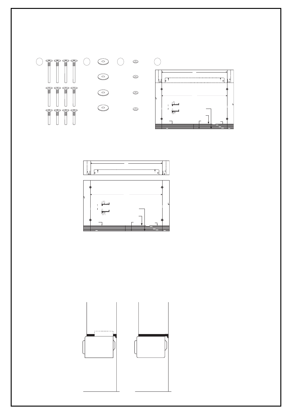
LISTA DE COMPONENTES
1. 3 juegos de tornillos
2. 4 arandelas-A
3. 4 arandelas-B
4. 1 plantilla
Cuando haya acabado de comprobar la lista de componentes, lea completamente las instrucciones antes de comenzar la instalación.
Esto le ayudará a familiarizarse con el proceso y hará que la instalación le resulte más fácil.
(NOTA: Le sugerimos que reúna todas las herramientas necesarias y los componentes de la instalación en un solo lugar.)
PREPARACIÓN
Abra la plantilla y separe los dos segmentos a lo largo de la línea de puntos con ayuda de unas tijeras. Con ello obtendrá dos piezas
distintas.
•
Plantilla 1
•
Plantilla 2
DOS MÉTODOS DE MONTAJE
Puede utilizar cualquiera de los dos métodos de montaje descritos en el folleto.
1.
Método sobre encimera
Use este método si decide no montar el horno en un armario.
Para usar el horno como un modelo de encimera, colóquelo sobre la parte de la encimera que desee y conecte el cable eléctrico a
un enchufe de pared de tres orificios (con toma de tierra).
2.
Método de montaje en armario
Este método se utiliza para montar el horno en un armario, y necesita la plantilla, las 4 arandelas y el juego de tornillos. Antes de
comenzar el procedimiento, debe retirar los cuatro botones de plástico situados en la parte superior del horno. Esto se consigue
introduciendo la punta plana de un destornillador fino entre el botón y la parte superior del horno y tirando suavemente, con cuidado para
no rayar la parte superior del horno.
EL HORNO PUEDE MONTARSE EN ARMARIOS CON O SIN TOPE FRONTAL.
If you drill the 4 mounting holes from the inside of the cabinet - place the
front edge of the template at the front edge of the cabinet.
Drill the 4 holes 1/4" DIA. as described in the installation instruction booklet.
If you drill the mounting holes from the bottom side of the cabinet -
measure the thickness of the front rail and cut that amount off the front of
the template. Use the cutting lines to insure a straight cut. Place the cut
edge against the back side of the front rail and position the template flat
against the bottom side of the cabinet.
Drill the 4 holes 1/4" DIA. as described in the installation instruction booklet.
IMPORTANT
Read the installation booklet for complete instructions before beginning installation.
Template must lay flat against the cabinet when locating the holes.
(See installation booklet for complete instructions.)
TEMPLATE 1
TEMPLATE 2
INSTRUCTIONS
15
25/64"
15
25/64"
DETACH
DETACH
TEMPLATE
CUT LINES
CABINET
FRONT
(A)
(B)
or
TEMPLATE
ON TOP SIDE
FRONT
FRONT
TEMPLATE
CUT LINES
1 1/4 INCH
1/2 INCH
1/4 INCH
1 INCH
CABINET FRONT
DET
ACH
HOLE CENTRE LINE
HOLE CENTRE LINE
MICROW
A
VE SIDE
MICROW
A
VE SIDE
HOLE CENTRE LINE
DET
ACH
HOLE CENTRE LINE
CABINET
FRONT
FRONT RAIL
THICKNESS
TEMPLATE ON
BOTTOM SIDE
CUT EDGE
1
2
4
3
TEMPLATE 1
TEMPLATE 1
15
25/64"
DETACH
DETACH
DET
ACH
HOLE CENTRE LINE
DET
ACH
HOLE CENTRE LINE
If you drill the 4 mounting holes from the inside of the cabinet - place the
front edge of the template at the front edge of the cabinet.
Drill the 4 holes 1/4" DIA. as described in the installation instruction booklet.
If you drill the mounting holes from the bottom side of the cabinet -
measure the thickness of the front rail and cut that amount off the front of
the template. Use the cutting lines to insure a straight cut. Place the cut
edge against the back side of the front rail and position the template flat
against the bottom side of the cabinet.
Drill the 4 holes 1/4" DIA. as described in the installation instruction booklet.
IMPORTANT
Read the installation booklet for complete instructions before beginning installation.
Template must lay flat against the cabinet when locating the holes.
(See installation booklet for complete instructions.)
TEMPLATE 2
TEMPLATE 2
INSTRUCTIONS
15
25/64"
TEMPLATE
CUT LINES
CABINET
FRONT
(A)
(B)
or
TEMPLATE
ON TOP SIDE
FRONT
FRONT
TEMPLATE
CUT LINES
1 1/4 INCH
1/2 INCH
1/4 INCH
1 INCH
CABINET FRONT
HOLE CENTRE LINE
HOLE CENTRE LINE
MICROW
A
VE SIDE
MICROW
A
VE SIDE
CABINET
FRONT
FRONT RAIL
THICKNESS
TEMPLATE ON
BOTTOM SIDE
CUT EDGE
CABINET
(SIDE VIEW)
COUNTERTOP
CABINET
(SIDE VIEW)
COUNTERTOP