Rear brake system, Rear brake system -6, System description – MEGA Corp. MES34-OPS-1 User Manual
Page 13: Mes34-ops-1
MES34-OPS-1
21 Feb 2014
SECTION 2
System Description
2-6
Floor Control (Joystick)
•
Left & Hold – opens floor fully.
•
Right & Release – auto closes floor.
•
Auto close can be interrupted by
commanding floor open and release.
Elevator Control (Thumb-switch)
•
Left – elevator rotates to load.
•
Right – elevator rotates to unload.
•
Speed increases the further the thumb-switch
is moved from center.
•
If a different elevator direction is desired with
“cruise control” on, elevator will delay for
about 3 seconds before reversing direction.
Transmission Hold (Outer Push Button)
•
1
st
Push & Release – prevents the
transmission from shifting.
When the transmission hold is engaged, an
indicator light will illuminate on the front
dash.
•
2
nd
Push & Release – normal shifting is
resumed.
Cushion Hitch (Inner Push Button)
•
1
st
Push & Release – enables cushion hitch.
•
2
nd
Push & Release – disables cushion hitch.
Elevator On/Off/Resume (Trigger Switch)
•
Pull bottom of trigger – engages “cruise
control” and holds existing elevator direction
and speed selected by thumb switch. If speed
and direction was previously set, pulling the
trigger will reestablish previous settings.
•
Push top of trigger – disengages “cruise
control”.
REAR BRAKE SYSTEM
The MES rear brake system is integrated with the
existing 631G tractor parking, service and emergency
brakes. All three systems are activated with the
existing brake controls located in the tractor cab. See
the CAT 631G Operator and Service Manual for
additional tractor brake information.
The MES rear brake system consists of a wheel group,
two additional air tanks, pneumatic manifold
assembly, pneumatic brake relay valve, brake pods,
solenoid valve, pressure switch, pressure sending
unit and hosing.
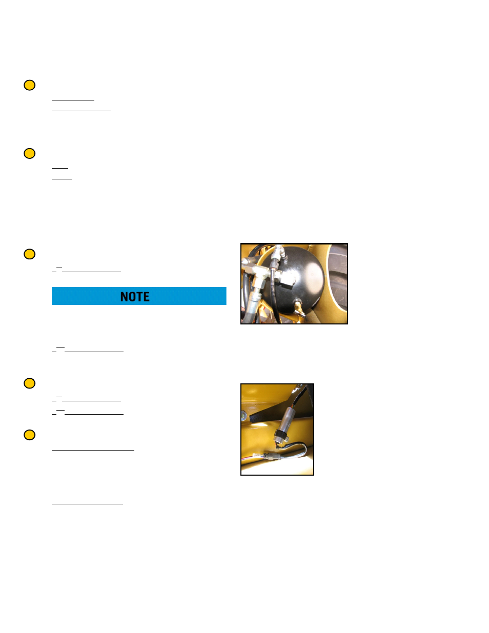
AIR TANKS
The MES is equipped
with two air tanks
mounted in the rear
bogie that store 100-
150 psi air. The tanks
are interconnected and
receive pressurized air
from the tractor
primary air tank that is mounted under the tractor
cab. Each tank is equipped with drain port to remove
moisture from the brake system.
TANK PRESSURE SENDING UNIT
A 24 VDC pressure sending unit
is mounted on the rear bogie
and is wired into the existing
tractor brake pressure indicating
and warning systems. The
sending unit provides air
pressure sensing for the tractor
air brake sensing in the tractor
cab. The sending unit also
provides a signal to the brake low pressure warning
system that sounds an audible warning tone when
brake supply pressure drops below allowable limits.
2
3
4
5
6