System description – MEGA Corp. MES34-OPS-1 User Manual
Page 14
MES34-OPS-1
21 Feb 2014
SECTION 2
System Description
2-7
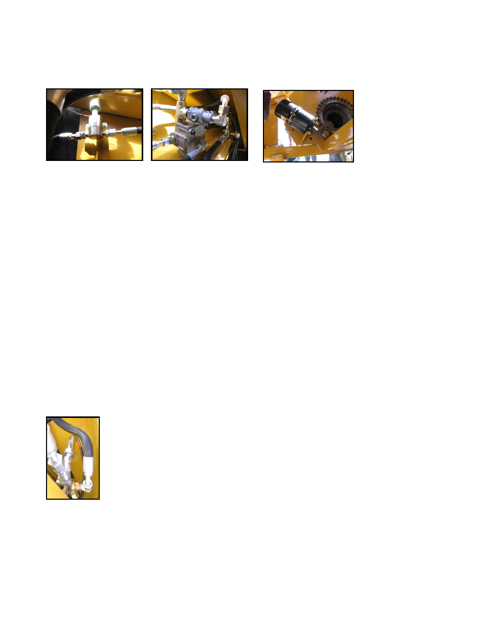
PNEUMATIC MANIFOLD ASSEMBLY
A pneumatic manifold mounted in the rear bogie
used to route pneumatic pressure for service, parking
and emergency brake operation. The manifold also
provides mounting for a check valve, parking brake/
emergency solenoid and parking brake pressure
switch.
CHECK VALVE
A spring operated valve allowing air flow in only one
direction. The valve is located with the pneumatic
manifold assembly in the rear bogie.
PARKING/EMERGENCY BRAKE SOLENOID
A 24 VDC electrical solenoid that opens or closes to
control the parking or emergency brake function.
The solenoid valve responds to electrical signals as
commanded by the parking or emergency brake in
the tractor cab. The solenoid valve will open to bleed
off parking/emergency brake release pressure from
the brake pods. This release of air pressure will cause
the parking/emergency brakes to be applied.
PARKING BRAKE PRESSURE SWITCH
A 24 VDC pressure switch used to
illuminate the parking brake warning
light in the tractor cab. The sensor will
turn on the parking brake warning
light when parking brake release
pressure drops below allowable
limits.
SERVICE BRAKE RELAY VALVE
A pneumatic relay valve that controls and routes air
tank activation pressure to both brake pods. The relay
controls air pressure applied to the brake pods as
commanded by a pneumatic signal pressure by
activating the service brake pedal located in the
tractor cab.
BRAKE PODS
A pneumatic cylinder
designed to extend or
retract and apply service,
parking or emergency
brakes. The pods are
mounted to the MES rear
bogie and are connected
to the wheel group brake activation lever. The pod
contains a coil spring and responds to pressure
received from the brake relay valve as commanded
by service brake pedal. The pod will also apply
parking or emergency brakes when one side of the
cylinder is depressurized when commanded by the
activation of the parking or emergency brakes. Loss
of pneumatic pressure allows the brake pod coil
spring to extend the rod end.
PARKING BRAKE THEORY OF OPERATION
The parking brake is applied by activating the
parking brake switch in the tractor cab. Once the
switch is moved to the park position an electrical
signal is sent to the parking brake solenoid valve
mounted on the rear bogie pneumatic manifold. The
sent signal will open the solenoid valve allowing
pneumatic pressure to decrease from one side of the
brake pod. The brake pod coil spring can now
overcome air pressure and extend the brake pod rod
end attached to the wheel group brake lever and
apply the brakes. Once parking brake pneumatic
pressure drops below allowable limits, the parking
brake pressure switch mounted on the pneumatic
manifold will close and illuminate the parking brake
warning light in the cab of the tractor.
The parking brake is released by activating the
parking brake switch. Once the switch is moved an
electric signal is sent to close the parking brake
solenoid valve. The valve closing will allow
pneumatic pressure from the pneumatic manifold to
be routed to the brake pod. This pressure increase
will eventually overcome the brake pod coil spring
and retract the brake pod cylinder rod end attached
to the brake pod releasing the brakes. As pressure
increases above allowable limits, the parking brake
pressure switch will turn off the parking brake
warning light in the tractor cab once pressure is
above allowable limits.