Measurement Computing DBK Part 2 User Manual
Page 39
DBK Option Cards and Module
899892
DBK43A & DBK43B, pg. 19
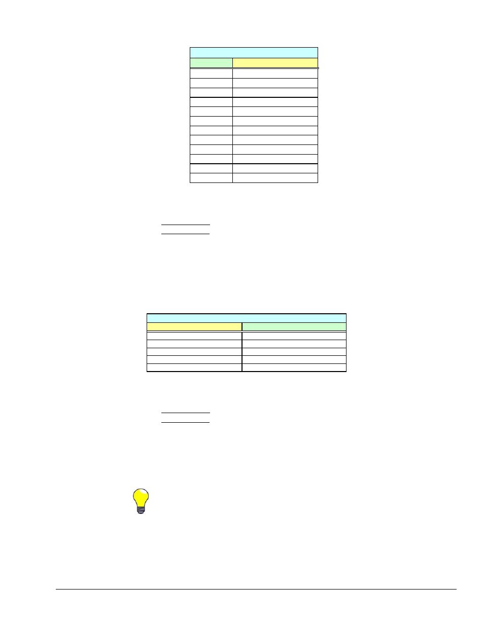
Typical input gain settings are shown in the following table.
Input Gains and Typical Readings
Input Gain
Reading
x100 0.5
volts
x200 1.0
volts
x300 1.5
volts
x400 2.0
volts
x500 2.5
volts
x600 3.0
volts
x700 3.5
volts
x750 3.75
volts
x800 4.0
volts
x900 4.5
volts
x1000 5.0
volts
x1200
6 volts *
* requires primary acquisition device to be in unipolar mode.
11. Adjust the Scaling Gain.
(a) DBK43A users: CAL/NORM switch remains in the NORM position.
DBK43B users: CAL1 remains “Down” (Run) and CAL2 remains “Up.”
(b) DaqView users: select “Scaling Gain” for the Channel Type.
LogView users: select “SetScalingGain” for the Mode.
(c) With the Reading column enabled, adjust the SCALE trimpot (SCA) for a voltage reading
equal to .005 x G
I
x G
S,
where “G
I
” is the desired input amplifier gain and “G
S
” is the
desired scaling amplifier gain. Note that each of the eight channels has a channel-specific,
trimpot for Scaling Gain.
(d) Stop the Readings.
Scaling Gains Typical with an Input Gain of x200
Scaling Gain
Reading
x2 2.0
volts
x4 4.0
volts
x6 6.0
volts*
x8 8.0
volts*
x10 10.0
volts*
* requires primary acquisition device to be in unipolar mode.
12. Adjust the Offset while the bridge circuit is being read.
(a) DBK43A users: CAL/NORM switch remains in the NORM position.
DBK43B users: CAL1 remains “Down” (Run). Position CAL2 “Down” (Run).
(b) Select “Bridge.”
(c) With the Reading column enabled, and with the quiescent (normal or inactive) load or strain
applied, adjust the OFFSET trimpot for a reading of 0.00 volts. This adds offset to the
circuit to compensate for the quiescent load and allows maximum resolution for the
measurement.
(d) After adjusting the Offset to 0.00, stop the Readings.
The Offset adjustment is unipolar 0 to 5 V on the input amplifier output. If the Offset can
not be adjusted to 0.00 V at the end of the setup procedure, swap the V
in
+ (4) and V
in
- (3)
wire connections, or reduce the Input Gain and increase the Scaling Gain.
13. If required for your application, enable the low-pass filters. The filters are set via jumpers JPn04
where n is the channel number (1 through 8); for example, JP104 sets the filter for channel 1, and
JP804 sets the filter for channel 8.
14. If required for your application, set AC Coupling. Coupling is set via jumpers JPn03 where n is the
channel number (1 through 8). To set AC Coupling, remove the JPn03 jumpers.