Setting into operation, Supply voltage, Input signals – Meinberg TCR511 User Manual
Page 10: Input for unmodulated codes, Input for modulated codes
10
Setting into operation
To ensure proper operation, please pay attention to the following points.
Supply Voltage
The boards microprocessor system needs a supply voltage of +5V / 200mA. Additional-
ly the Oscillator supply voltage ( +5V or +12V depends on type ) must be applied via
64pin VG connector. The voltage feed shall be low impendance and for each of the
voltages pins a + c at VG connector shall be used.
Input Signals
Modulated IRIG or AFNOR-Codes are applied via the on board SMB connector. The
lead should be shielded. Unmodulated codes are applied at Pins 21c ad 22c of the 64pin
VG connector. Voltages applied to this input shall not exceed 12V. The IRIG-Code to
be used must be set at the DIP Switch.
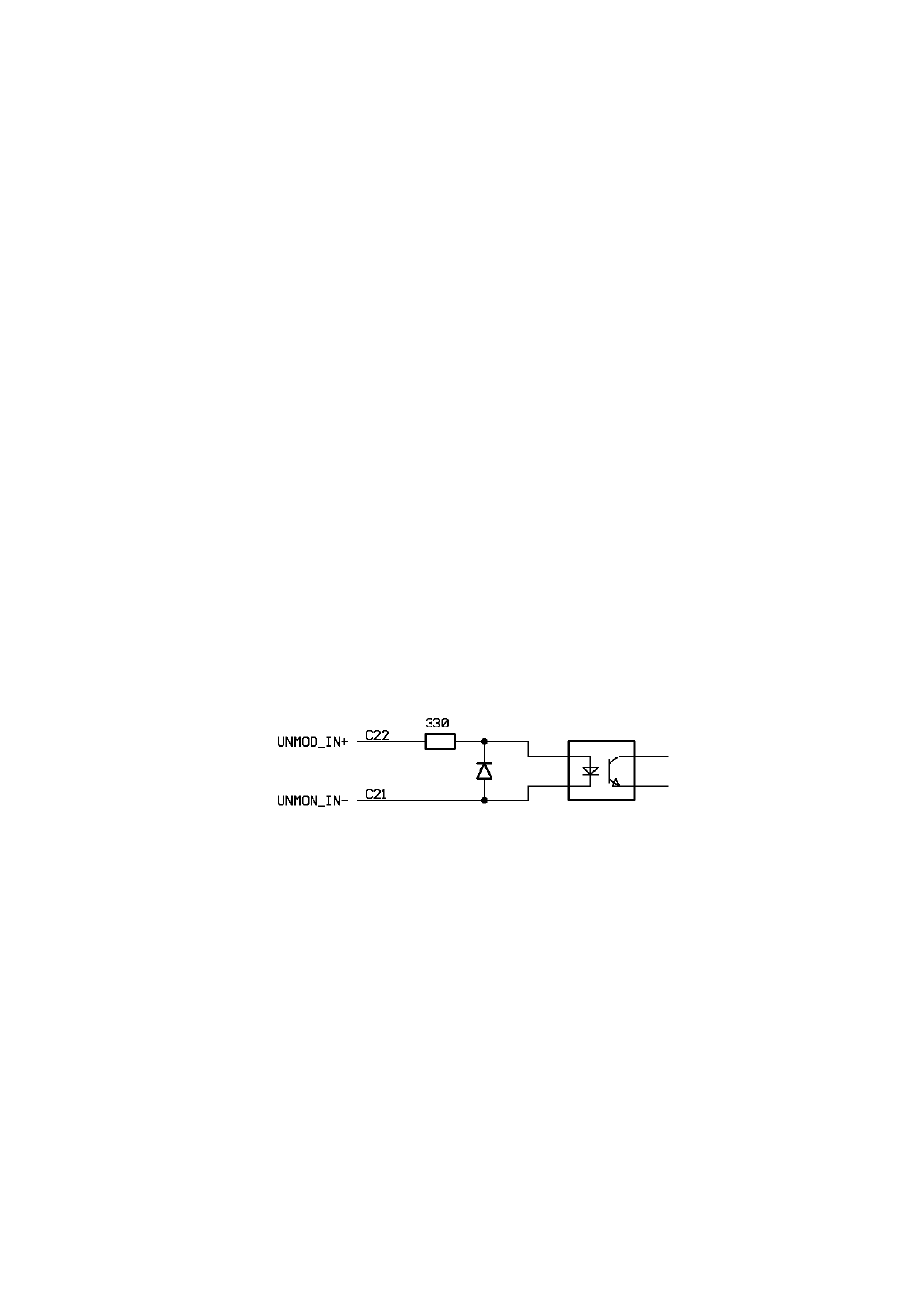
Input for unmodulated codes
Unmodulated IRIG-Codes, often referred to as pulse with coded or DC-Level Shift
Codes ( DCLS ), are fed into the board via pins C21 and C22 off the 64pin VG
connector. Insulation of this input is done by a opto coupler device. The input circuitry is
shown below.
Input for modulated codes
Modulated codes must be applied to the on board SMB Connector. An automatic gain
control allows decoding of codes within an amplitude range from abt. 600mVpp up to
8Vpp. To allow adaptation of different time code generators, the boards input impedance
can be selected by an on board jumper.