Serial output specification, Page 15 – MicroE 3500Si Mercury User Manual
Page 17
Serial Output Specification
Page 15
Important Notes:
The user must wait 1180ns after a trigger for the data acquisition to make its way through the position calculator. After the 1180ns calculation
latency the position number is available at the serial output buffer.
This position number is valid for 340ns before the calculator pipeline overwrites the value in the serial output buffer. Asserting the n_spiEnable
within 340ns of data being valid will freeze the serial output buffer for data transfer.
n_spiEnable is sampled by an internal clock when in the Trigger Approach mode. The uncertainty of this measurement is 80ns.
When not in the trigger mode, n_spiEnable is not sampled by an internal clock and there is no synchronization of the interpolator calculation to an
external event. The uncertainty of this measurement is 340ns.
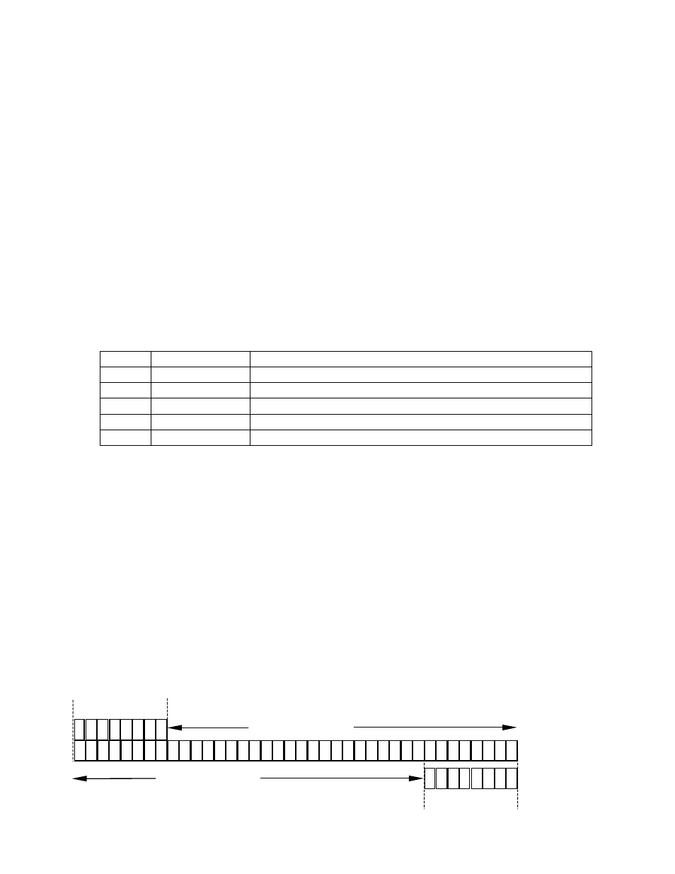
Data Format:
The data word, which is made up from the position and status words, are transferred with the most significant bit (MSB) first. The data word
length is 38 bits wide .
Status Word:
The status word is 8 bits wide. The status word may be placed either before or after the position word within the data word. The Status word
placement can be set using the optional SmartPrecision Software.
Bit
Name
Description
0
redAlarm
asserted low if signal level is out of range
1
yellowAlarm
asserted low if signal level is near out of range
2
indexMode
asserted high indicates index angle in acquire mode
3
indexWindow
asserted high when encoder is within physical window
4 to 7
reserved
Status Byte Definition:
Example: 0000_0011 (Normal Operation)
Position Word:
The position word is 30 bits in length. The position word is made up of an 18 bits of fringe data and 12 bits of interpolation data.
Fringe Data: (Programmable up to 18bits)
The fringe counter keeps track of the number of electrical cycles encountered caused by a grating moving past a sensor. The size of the fringe
counter is programmable from 3 bits wide to 18 bits wide (factory default). The width is selectable through the optional SmartPrecision Software.
Reducing the size of the fringe counter will increase the overall sample rate of the system. At 18 bits, the counter is large enough to keep track of
a grating length of 5.24 meters.
Note: The fringe counter size should be larger than the anticipated range of motion to guarantee that the counter will not "roll over".
In normal operation, the fringe counter can "roll over" to a negative number with a small amount of movement upon power up.
Interpolation Data: (Lower 12bits)
The interpolation depth of the SS350SI is always 4096. If the user prefers smaller interpolation depths then fewer spiClock signal clocks can be
sent to the interpolator and fewer bits will be shifted out. This will also increase the maximum sample rate for the system.
3
1
3
0
2
9
2
8
2
7
2
6
2
5
2
4
2
3
2
2
2
1
2
0
1
9
1
8
1
7
1
6
1
5
1
4
1
3
1
2
1
1
1
0
9 8 7 6 5 4 3 2 1 0
3
4
3
3
3
2
8bit status
format 0
3 2 1 0
5 4
6
7
30bit Position Word
format 0
3
5
3
7
3
6
8bit status
format 1
3 2 1 0
5 4
6
7
30bit Position Word
format 1
38 bit word