Clearances, Installing the standoffs, Nailing flange extension – Montigo H38DF PFC User Manual
Page 8: Installing the standoffs nailing flange extension, Installation
Page 8
XG0816 - 150204.1
H*38DF PFC Peninsula Gas Fireplace
Installation
Clearances
When installing a shelf over the top of the fireplaces, the following
guidelines must be adhered to:
For Rear Vent applications, the minimum clearance is 2" from the rear of
the fireplace to a wall, or any combustible materials, and 11" clearance
from the top of the fireplace to the underside of any combustible shelf
materials.
For Top Vent applications, the minimum clearance is 2" from the rear of
the fireplace to a wall, or any combustible materials, and 17 1/2" to the
underside of any combustible shelf materials.
For Horizontal vent pipes, ensure that 1” clearance is maintained on
sides and bottom of vent runs and 2” above horizontal vent runs to any
combustible material.
MODEL
Top - Rear vent
†
Top - T
op vent
†
Rear
Sides
Floor
Mantel
H*38PF*
11"
17 1/2"
2"
1"
0"
See Section 6:
Finishing around
the fireplace
Installing The Standoffs
To avoid elevated mantel temperatures, all H*38PF*-Series gas
fireplaces are required to have the supplied standoffs installed.
The fireplace is supplied with two standoffs. Bend and install these
standoffs on top of the fireplace ensuring that the height of the standoff
maintains a 8" clearance.
† Note: Clearance from top of fireplace to a ceiling within the fireplace
enclosure.
8”
Fasten Standoffs
in gutter
Figure 6� Installing the standoff's.
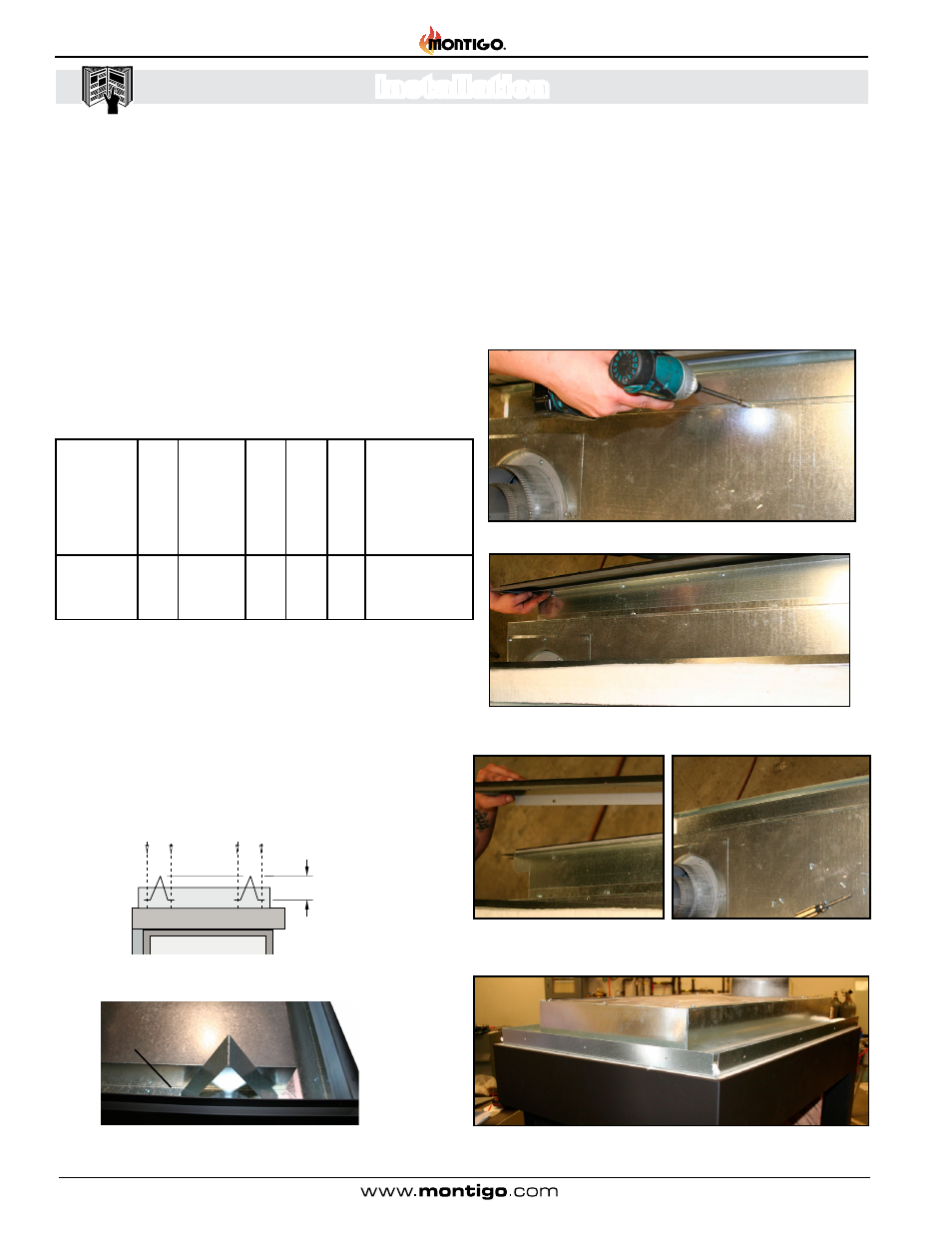
Nailing Flange Extension
The 4" nailing flange extension is shipped attached to the top edge of
the fireplace, see Figure 1.
The nailing flange extension may be substituted with a piece of NON-
Combustible material of the same thermal characteristics, ie: cement
board or equivalent to fit the opening. This is recommended in applications
where the facing materials will not adhere to the metal nailing flange.
To remove the Nailing Flange Extension follow the directions below:
Figure 7c� Finished removing Nailing Flange extension.
Figure 7� Remove screws from top of the unit
Figure 7a� Remove shell and insulation from the top of unit. Remove screws
from outer edge.
Figure 7b� Remove the nailing flange extension from the unit. Reinstall shell
and insulation. Screw shell in place.