Section 3-3-1: venting layout, Installation – Montigo H38DF PRC User Manual
Page 13
H*38DF PRC Panorama Indoor Gas Fireplace
Page 13
XG0211 - 150204.1
Installation
MTKOG (5"/8")
Installing Heat Guards over Terminations
is recommended
in installations where the termination is located within 7' feet above
grade, or above a pedestrian walkway, and may be Required by code
in Public areas.
1. Ensure that the two long mounting brackets are facing the bottom
of the termination. (See inset). This will provide more heat protection
at the top of the termination, where temperatures are highest.
2. Attach to the faceplate of the termination using four sheet metal
screws.
Figure 11. Installing a PTO termination heat guard.
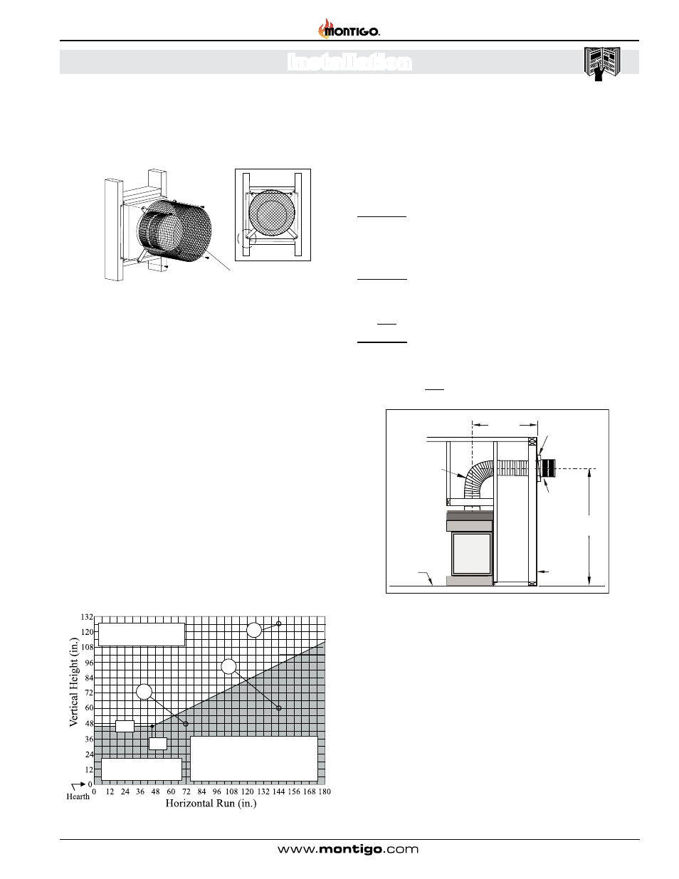
Figure 12. H38PR* or HL38PR* Top Vent Venting Graph for wall mounted
terminations.
Section 3-3-1:
VENTING LAYOUT
Selection of components and details of venting layout should
adhere to the following guidelines:
Vent terminations must not be recessed in walls or siding.
For Heat Shield requirements see Section 3-3-3 on page 17.
Once the proposed venting layout has been determined refer to
either Figure 12, 12a, 14, or 14a to ensure the layout is acceptable.
Notes Wall Mounted Terminations: TOP VENT
All dimension lengths for vertical or horizontal runs are measured
from center of the vent pipe.
Venting runs must fall within the limits set by the venting graphs,
see Figure 12 or 12a.
Figure 12a. H38PR* or HL38PR* Top Vented, wall mounted installation with
one 90° bend. The vent run must comply with Venting Graph for Top vent, wall
mounted terminations, Figure 12.
42”
46”
A
C
B
If your installation does not fall with-
in the venting graph parameters,
please contact a local Montigo
dealer for Power Venting options.
Unacceptable vent run
within shaded area.
Acceptable vent run
within non-shaded area.
Heat
Shield
Termination
Hearth
Exterior
Wall
46”
Min.
42” Max.
Flex section
The Venting Graph
Measure the vertical height from the fireplace hearth to the centre of
the termination and the horizontal run from the fireplace flue collar to
the wall flange of the termination. Plot on the Venting Graph Figure 12
or 12a with an 'X'.
If the 'X' falls on or above the top boundary of the shaded area, the
installation is acceptable.
Example A: (Acceptable Installation)
If the vertical dimension from the hearth is 126" and the horizontal
run to the wall flange of the vent termination is 144", this would be
an acceptable installation.
Example B: (Unacceptable Installation)
If the vertical dimension from the hearth is 48" and the horizontal
run to the wall flange of the vent termination is 72", this would
NOT be an acceptable installation.
Example C: (Unacceptable Installation)
If the vertical dimension from the floor of the fireplace is 60" and
the horizontal run to the wall flange of the vent termination is 144",
this would NOT be an acceptable installation.