Installation – Montigo EDVWSPV47 User Manual
Page 7
Page 7
EDVWSPV Horizontal Power Vent System
Part No. XG1303 - 120110
Installation
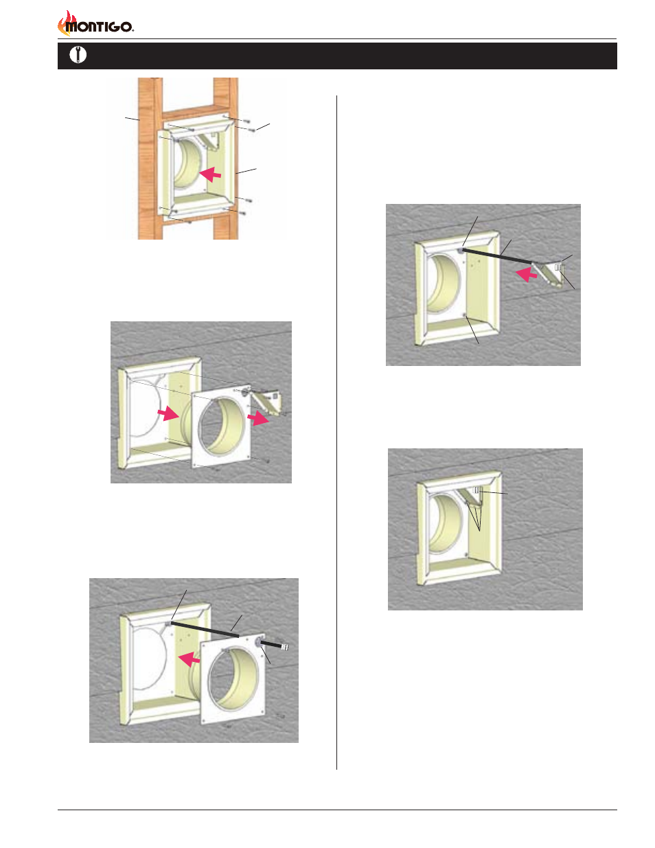
Figure 6. Installation of Rough-in Kit
Figure 7. Installation of Power Vent Conduit
Step 3.
Next, remove the bottom collar and conduit mounting frame as
shown Figure 6. (Place removed hardware in a handy location
for re-assembly).
Figure 5. Orientation, Placing the Power Vent Inner Box
Framing
Rough-in Frame
Fasteners
Power Vent Conduit
Strain Relief
Nut
Step 4.
Insert the conduit from the Power Vent Module into the rough-in
frame through the two top right entry holes. Remove the nut from
the supplied strain relief and place as shown, Figure 7.
Strain Relief
Figure 7. (Installing Conduit connector & conduit mounting frame)
Figure 8. (Assembled Rough-in Kit)
Step 7.
Fasten Conduit mounting frame into place using existing hard-
ware, (6-pcs). (Coil conduit in behind cover.)
Step 8.
Install the Power Vent Power / communication harness. Hold the
Power Vent in close proximity of the assembled Rough-in Kit,
and plug in the Power Vent communication / Power Cord. (Note
the direction and orientation of the pins inside the Power Vent
connector, snap together). (Figure 9).
Power Vent Conduit
Strain Relief & tightened nut
Power Vent
Connector
Conduit
mounting
frame
Step 5.
Securely fasten bottom Collar pan into the Rough-in frame using
the existing hardware, (4-pcs). Tighten Strain Relief nut onto
Strain relief.
Step 6.
Pull Power Vent Connector, (from behind) half-way through
supplied hole in conduit mounting frame, and snap into place,
(notches in two plastic wing clips. Orientation not critical).
Tightened hardware,
6-pcs.
Installed Power
Vent Connector
Tightened hardware,
4-pcs.