/ natural gas and propane piping, / venting, Offset box – Montigo 36DRG User Manual
Page 3
Page 3 of 11
36DRG
09/96
3./ NATURAL GAS AND PROPANE PIPING
A.) All gas piping shall be in accordance with the
current CAN/CGA B149.1 and .2 installation
codes and installed by a qualified professional
gas fitter technician.
Inlet pressure N/G 7.0 W.C.
Minimum natural gas inlet pressure 5.0" W.C.
Manifold pressure 3.5" W.C.
This appliance has been set for 28,000 BTUH at
Sea level rating for natural gas and 27,000 BTUH
for propane and is CGA certified for altitudes
between 0 - 2000 feet without an orifice change
and 2000 - 4500 feet with an orifice change. The
orifice required for high altitude must be supplied
by the manufacturer.
The minimum inlet gas supply pressure permissi
ble is 11" W.C. for propane.
GAS NATURAL PROPANE
Manifold Pressure 3.5" W.C. 10.5" W.C.
Minimum Supply Pressure 5.0" W.C. 11" W.C.
B.) Ensure that the gas supply pipe is adequate for the
appliance capacity. A 1/8 inch plugged tapping
must be provided immediately upstream of the gas
supply connection to the appliance for test gauge
connection.
After gas line is connected, it is a CAN/CGA B149 code Requirement
(Section 8.25.3(e)) that: “each appliance Connection, valve, valve train,
shall be checked while under normal pressure with either a liquid solution
or leak detection device, to locate any source of leak.” Tighten any areas
where bubbling appears or leak is detected until Bubbling stops com-
pletely. DO NOT use a flame of any kind to test for leaks.
4./ VENTING
It is recommended that the chimney be thoroughly
cleaned before installation and checked for soundness
and general condition.
For proper installation, the use of a 4 inch (100 mm)
diameter gas approved chimney liner is needed. This
is to provide appropriate draft and avoid excessive
corrosion In the combustion chamber and heat ex-
changer of the appliance.
Before installing the vent system, ensure that the
damper plate is locked into the open position and
secured to prevent the damper plate from crushing
the liner.
(See Drawing #1)
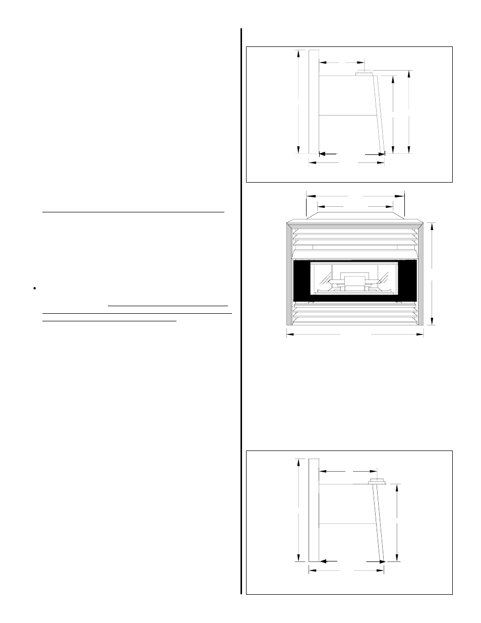
FIREPLACE DIMENSIONS:
2 3/4"
HEIGHT:
21 1/4"
WIDTH:
28"
DEPTH:
13 5/8"
○
○
○
○
○
○
○
○
○
○
○
○
○
○
○
○
○
○
○
○
○
○
○
○
○
○
○
○
○
○
○
○
○
○
○
○
○
○
○
○
○
○
○
○
○
○
Drawings - #2a, #2b and #2c (with add on)
DRAWING #2c
11"
26 3/8"
21 1/4"
16 1/8"
DRAWING #2b
OFFSET BOX
Extends flue collar an additional 3". For applications
which require the flue collar to be extended, please
order part number 36DRG Offset Box. Installation
instructions for this offset box are included with the
offset.
8"
21 1/4"
24"
26 3/8"
DRAWING #2a
16 1/8"
13 5/8"
OFFSET BOX
13 5/8"
17 1/4"
28"
26 3/8"
38 3/16"