Maintenance, Gas control valve, Pilot burner adjustment – Montigo C34 VF User Manual
Page 9: Troubleshooting, Wiring for the optional fan kit
Page 9
C34-VF Gas Fireplace
Part No. XG0316
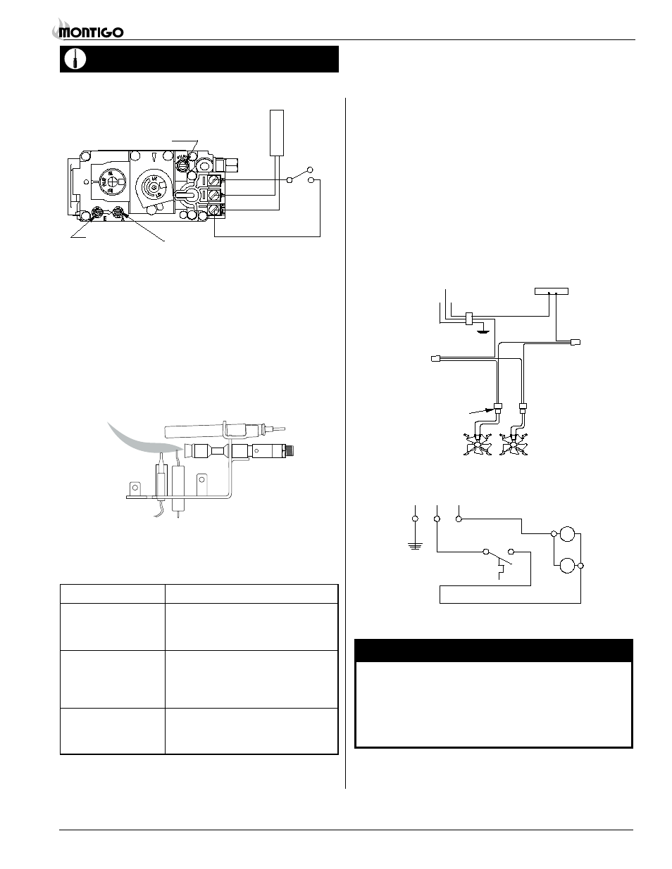
Maintenance
Gas Control Valve
Figure 11.
SIT NOVA 820.637 for NG, SIT NOVA 820.636 for LP.
Pilot Burner Adjustment
1. Locate Pilot Adjustment Screw. (See figure 11.)
2. Adjust pilot screw to provide properly sized flame as shown in
figure 12).
3. After installing or servicing, leak test with a soap solution with
main burner on. Coat pipe and tubing joints, gasket etc. with soap
solution. Bubbles indicate leaks. Tighten any areas where the
bubbles appear until the bubbling stops completely.
Figure 12.
Pilot Burner
Manifold Pressure
Test Connection
Pilot Adjustment Screw
Inlet
Pressure
Power
Generator
Wall Switch
Troubleshooting
The following is a troubleshooting chart of possible problems:
PrOBleM
COrreCtIVe ACtION
Noisy Pilot Flame
Locate pilot adjustement screw on
gas control valve. Flame is decreased by
turning adjustment screw clockwise.
Pilot won’t ignite
Disconnect remote wires and try to
light pilot. If pilot now works, remote
connections are faulty. Check wiring
diagram figure
11.
Main burner will
1. Check wiring (see figure 11).
not light
2. Check wall switch for proper con-
nection.
Figure 13a.
Wiring for optional air circulating fan kit.
G
L2-WH
L1-BLK
Quick Connect
plug to motor
Wiring for the optional Fan Kit
All C34-VF fireplaces may be equipped with an optional fan kit (Part
no. RFK1002 or RFK1003)for circulating heat into the living space.
Kits are available with manual or heat-activated control.
Installations which employ the fans must be grounded in accordance
with local codes or, in the absence of local codes, with the National
Electrical Code, ANSI/NFPA 70-1987.
For more information see the Fan Kit Installation guide included
with the fan kit.
NOTE:
If any of the original wire as supplied with the appliance must
be replaced, it must be replaced with a wire of at least a 60 º
temperature rating.
Figure 13b.
Wiring schematic for optional fan kit.
115/1/60 Supply
G
L1 L2
WARNING:
Do not allow fans to blow directly into the fireplace. Avoid
any drafts that alter burner flame patterns.
Do not use a blower insert, heat exchanger insert or other
accessories not approved for use with this heater.