Installation, Installation of rear vent dv – Montigo C42DV User Manual
Page 10
Page 10
C42-DV Gas Fireplace
®
Part No. XG0119C
Installation
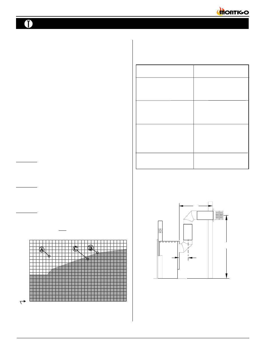
B. Multi-Elbow Installations
For more diffiicult installation situations, the C42-DV Rear Vent may
be installed with two — 90° elbows and up to 15' of horizontal run. If
using this installation option, you must adhere to the following
guidelines:
n
the first 90° elbow must be placed directly on the flue collar
n
you must have a minimum vertical lift of 50" (measured from
the hearth)
n
your vent run must fall within the limits set by Figure 18a
Before you install any venting, you must determine whether the
venting run will be acceptable. Unacceptable venting can affect the
fireplace's combustion.
The Venting Graph
Measure the vertical height from the fireplace hearth to the centre
of the termination and the horizontal run from the from the fireplace
flue collar to the wall flange of the termination. Plot on the Venting
Graph (Fig. 18a) with an 'X'.
If the 'X' falls on or above the top boundary of the shaded area, the
installation is acceptable.
Example A: (Acceptable Installation)
If the vertical dimension from the hearth is 84" and the
horizontal run to the wall flange of the vent termination is 36",
this would be an acceptable installation.
Example B: (Acceptable Installation)
If the vertical dimension from the hearth is 90" and the
horizontal run to the wall flange of the vent termination is 126",
this would be an acceptable installation.
Example C: (Unacceptable Installation)
If the vertical dimension from the floor of the fireplace is 78"
and the horizontal run to the wall flange of the vent termination
is 108", this would NOT be an acceptable installation.
Figure 18a.
C42-DV Rear Vent Venting Graph
0
12 24 36 48 60 72 84 96 108
132
120
144 156 168 180
Horizontal Run (in.)
Hearth
0
12
24
36
48
60
72
84
96
108
Installation Of Rear Vent DV
C42-DV Rear Vent versions are supplied with an PXT-20 (female/
female) section. In addition, the following venting components are
available for Rear Vent installations:
A - Termination
PTO-3 (3" length)
PTO-3F (3" length)
B - Stucco Kits
MSR (stucco frame)
BSR-4 (4" brick frame)
BSR-6 (6" brick frame)
MOSR (stucco can)
C - Flex sections
PFL-1 (12" section)
PFL-2 (24" section)
PFL-3 (36" section)
PFL-4 (48" section)
D - Solid sections
PEXT-1 (12" section)
PEXT-2 (24" section)
PEXT-3 (36" section)
PEXT-4 (48" section)
E - 90 degree elbow
PEL-90MM (m/m 90° elbow)
PEL-90FF (f/f 90° elbow)
PEL-90FM (f/m 90° elbow)
PEL-45FM (f/m 45° elbow)
Figure 18b.
Multi-elbow installation. Distance 'H' must be a
minumum of 50". The vent run must comply with figure
18a.
NOTES:
All dimension lengths for vertical or horizontal runs
are measured from center of the vent pipe.
Venting runs
must fall within the limits set by the
venting graph (see Figure 18a).
8"
H
L
18"