MultiDyne HD-3500 Series User Manual
Page 8
Instruction Manual, HD-3500 Series
FEATURES and OPERATION 5
REV F, April 1, 2015
RECEIVER, HD-3500-FRX
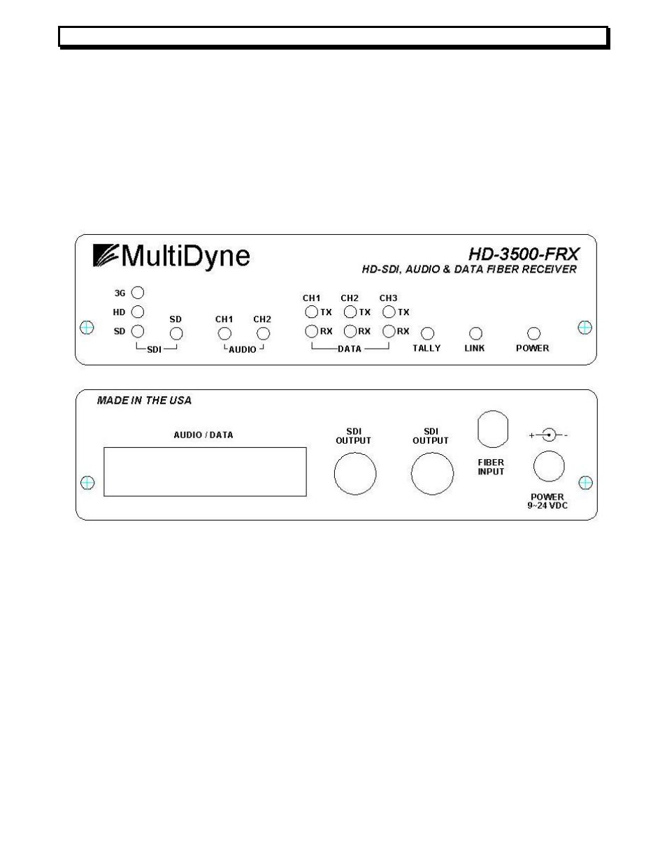
The receiver module front and back is shown in figure 3. In the back and from left to
right it includes: a DB44 connector for all audio and data IO, two SMPTE serial digital video
75 Ohm output BNC connectors for two reclocked SDI / HD-SDI outputs, a single fiber output
ST or SC connector, and a DC Jack power connector. In the front of the module we see three
SMPTE lock LEDs for 270 Mbps, 1.485 Gbps, or 2.970 Gbps rates; Fiber Signal Detector
LED. Also included are 2 audio status LED that indicate channel 1 and 2 level and peak; 6
data activity LEDs to indicate TX and RX activity in the 3 data channels; a tally on indicator
LED; a link status LED; and a power LED.
SMPTE transport
The HD-3500-RX receives the SMPTE video or other high-speed signals multiplexed
along with audio and data from the fiber connector. These signals are optically de-
multiplexed, and then sent to a reclocker to clean high frequency jitter created by return loss
and fiber interfaces. The signals are then buffered and sent to the two 75-Ohm outputs with
BNC connectors in the rear of the unit. Like in the TX side, the re-clocking capabilities work
automatically when SMPTE rates are detected. The front rate LEDs indicate that a valid
SMPTE video rate is locked by the re-clocker PLL. The Signal Detector (SD) LED indicates
that a light signal has been applied to the optical interface and status. If the LED lights red, it
means that the signal is heavily attenuated; typically less than -21dBm, there is nothing
active connected on the fiber port, or the fiber is broken. A yellow light means the optical
power is attenuated, typically less than -17dBm, but the link is still is operative probably due
to a long run of fiber or attenuation in the path.
Figure 3. Front and Back of HD-3500-FRX