MultiDyne HD-3500 Series User Manual
Page 9
Instruction Manual, HD-3500 Series
FEATURES and OPERATION 6
REV F, April 1, 2015
Non-SMPTE transport via the SMPTE interface
This unit should work normally by default with SMPTE video signals at the rates indicated
previously; however, other signals may need special settings. The reclocker will mute the
output when noise or a not supported SMPTE rate is detected. This feature can be disabled
when using other rates by setting SW4 on the PCB. Non-SMPTE standard signals should
automatically put the reclocker in bypass mode; however, in some instances, if the signal has
components close to the SMPTE frequencies, there may be glitches on the operation. To
avoid this, there is another setting for SW4 to force the reclocker into bypass mode. See
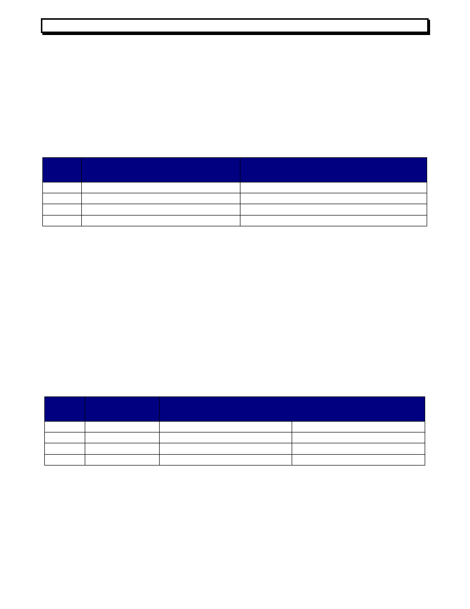
table 4 for SW4 settings.
Sw4
Position
ON Setting
Off Setting
1
Not Used
Not Used
2
Not Used
Not Used
3
Force reclocker bypass
Reclocker operates automatically with SMPTE rates
4
Disable SMPTE Auto-mute
SMPTE Auto-mute is on, use only with SMPTE
Audio Transport
This link transports two balanced stereo pairs, or two AES channels of high quality
audio. In the RX side, for each stereo pair, and whatever signal either analog or digital was
selected at the TX side, is sent simultaneously to the analog and digital AES ports. This
feature effectively can convert an analog signal in the TX side to digital in the RX side, or the
reverse case. The AES channels can be set for 110 ohms balanced output mode or 75 Ohms
singled ended output (see table 5). On the other hand, the analog stereo pairs can be set for
different Full Scale (FS) levels using a dip switch (see table 6). The audio LEDs in the RX
side indicate two possible statuses: green indicates analog level is present with a level from
-8dBFS to -1dBFS, and red indicates clipping. Even if a tiny clip is detected, the red LED is
held for a fraction of a second. In addition to these main audio channels, there is a
bidirectional stereo channel for intercom applications. This channel has unbalanced inputs,
and a maximum audio range of +4dBuFS.
Sw 2
Position
Function
Setting (Default values in Bold)
1
AES 1 Output
on = 110 Ohms AES3 Bal. Input
Set off when position 2 = on
2
AES 1 Output
on = 75 Ohms AES3id Single Input
Set off when position 1 = on
3
AES 2 Output
on = 110 Ohms AES3 Bal. Input
Set off when position 4= on
4
AES 2 Output
on = 75 Ohms AES3id Single Input
Set off when position 3 = on
Table 5. Settings for AES Audio outputs
Table 4. SW4 Settings