Interfaces – Norsat O3b 5W BUC User Manual
Page 7
Advertising
Rev. 1.0
7005STC-O3B Series
DES007565
7
2. INTERFACES
2.1
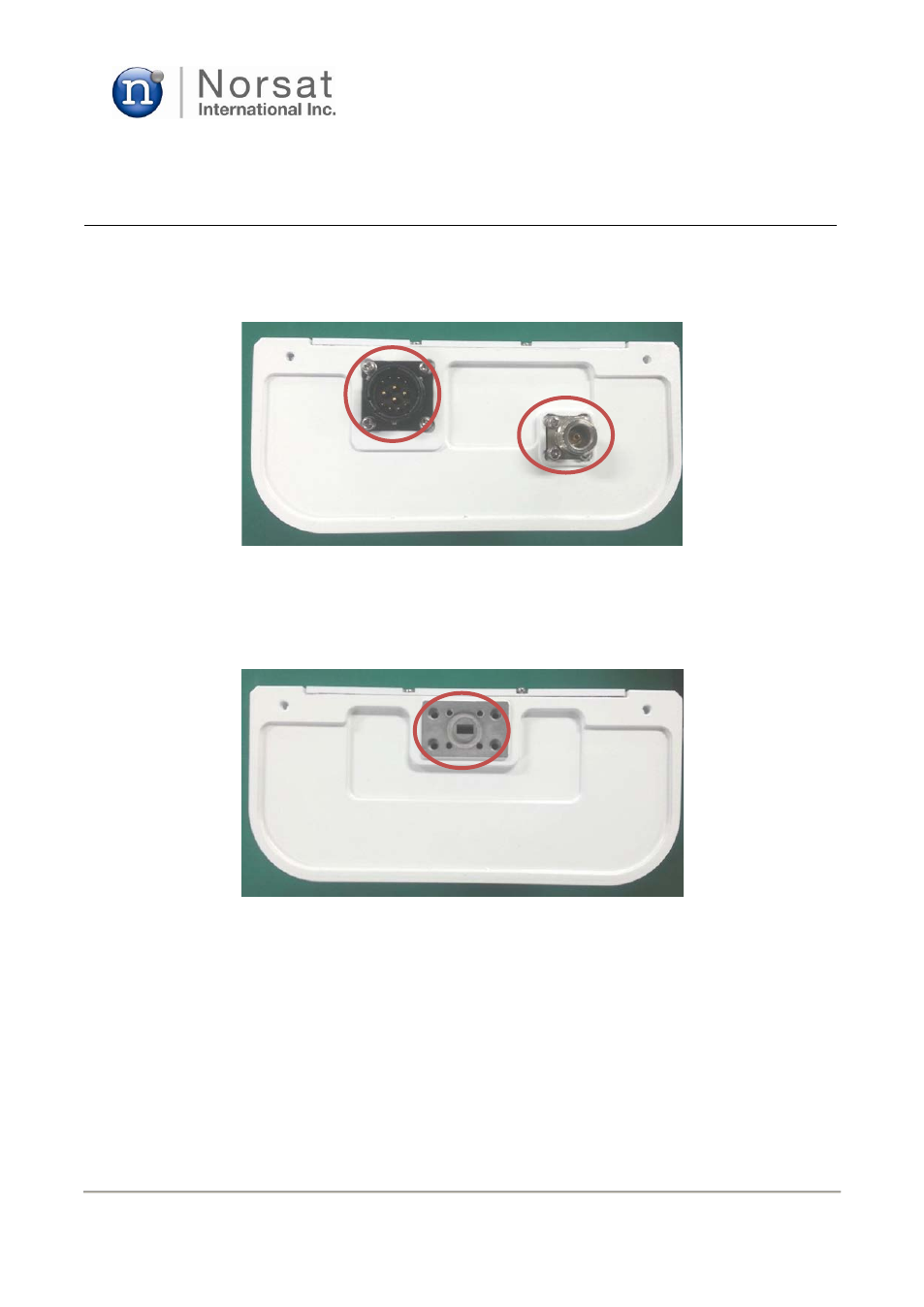
J1 / IF IN
N-type connector is used for the input port as shown in Fig. 2.
Figure 2. N-type IF and MS 12-pin connectors for Ka-band 5W BUC
2.2
J2 / RF OUT
WR28 waveguide is used for the output port as shown in Fig. 3.
Figure 3. WR28 RF output port for Ka-band 5W BUC
MS 12-PIN
Connector
N-type IF
Connector
(Input)
WR28 RF port
(Output)
Advertising