Norsat O3b 5W BUC User Manual
Page 8
Rev. 1.0
7005STC-O3B Series
DES007565
8
2.3
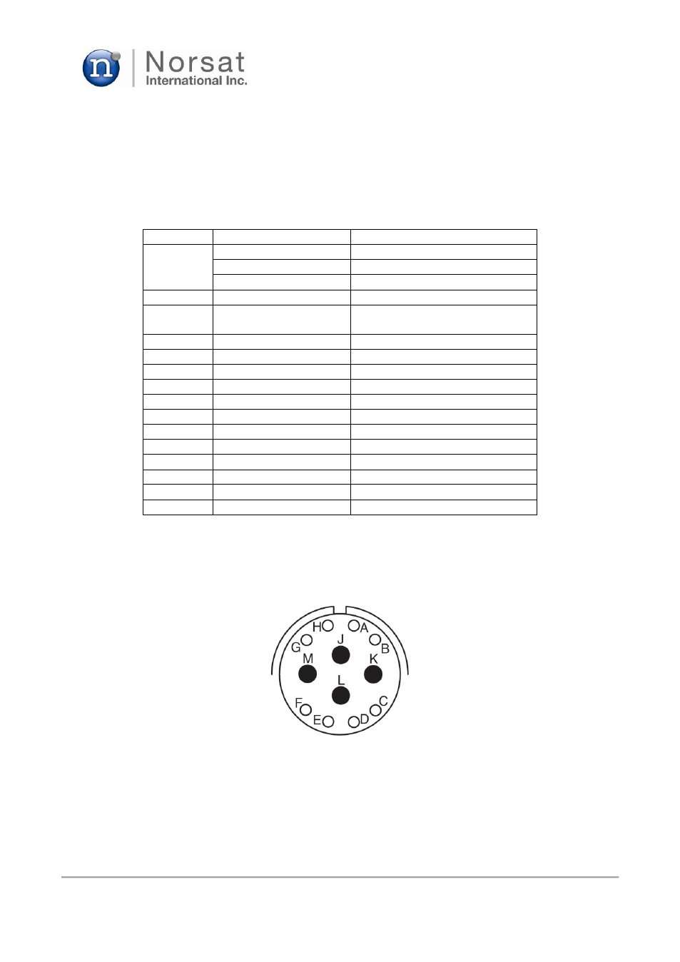
J3 / DC, M&C
MS 12-pin connector is used for the DC and M&C port as shown in Fig. 2, and its pin map
and interface are indicated in Table 1 and Fig. 4, respectively.
Table 1 Pin description for IF, RF, M&C connectors
Connector
Parameter
Description
J1
IF input connector
N-female, panel-mounted
Impedance
50 ohm
10MHz reference input
J2
RF output connector
WR28
J3
DC / M&C(Ethernet
or RS232)
Panel-mount (MS3112e14-12P)
J3-A
Ethernet Tx-
J3-B
Ethernet Tx+
J3-C
Ethernet Rx+
J3-D
Ethernet Rx-
J3-E
J3-F
RS-232 GND
J3-G
RS-232 TxD
J3-H
RS-232 RxD
J3-J
DC Power (+36 to +72V)
J3-K
DC Power return
J3-L
Mute @ High-Z or +5V
J3-M
Mute return (=RS-232 GND)
Figure 4. Physical interface of MS 12-pin connector