Installation, Lp-dc234 block diagram – Olson Technology LP-DC-X User Manual
Page 6
025-370447 REV X2
Page 6 of 10
The next picture is a block diagram of the LP-DC212. This unit contains the optical receiver and the band 3
converter. It also contains the 4.5MHz pilot extraction circuitry, which is used for AGC and phase lock. It supplies
the pilot and the full RF input spectrum to the LP-DC234.
Optical
Receiver
Front Panel
T.P. 1V/mW
4.5 MHz / AGC
Fiber Input
AGC
Rear 4.5MHz
to LP-DC 234
Amp
Filter
Front Panel
Full Spectrum
-20dB T.P.
Front Panel
AGC T.P.
Rear Panel
Full Spectrum
to LP-DC234
Rear Panel
Band 1 Output
Front Panel
Band 1 -20dB T.P.
Converter
Front Panel
Band 3 -20dB T.P.
Rear Panel
Band 3 Output
VCXO
Analog & Digital Status Monitoring
LP-DC212 Block Diagram
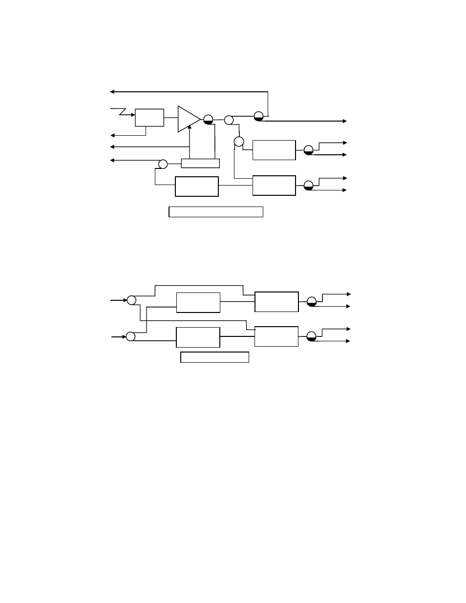
The next picture is a block diagram of the LP-DC234. This unit contains the band 2 and band 4
converters. This unit does not have an optical receiver and is not a self-contained unit. It must be connected to a
LP-DC212 to function.
Rear 4.5MHz
from LP-DC212
Converter
Front Panel
Band 4 -20dB T.P.
Rear Panel
Band 4 Output
VCXO
Digital Status Monitoring
Converter
Front Panel
Band 2 -20dB T.P.
Rear Panel
Band 2 Output
VCXO
Rear Panel
Full Spectrum
from LP-DC212
LP-DC234 Block Diagram
INSTALLATION
OPTICAL CONNECTORS AND CLEANING
The standard optical connector is an SC/APC. The fiber ends can be damaged by the insertion of
contaminated connectors. Some types of customer damage to connectors or fiber are not covered under warranty.
Fiber connectors should never be left uncovered. Reel cleaners or prepackaged alcohol wipes are the most
convenient means of cleaning optical connectors. Clean alcohol and lint free wipes or swabs may also be used.