Lp-dc212 – Olson Technology LP-DC-X User Manual
Page 8
025-370447 REV X2
Page 8 of 10
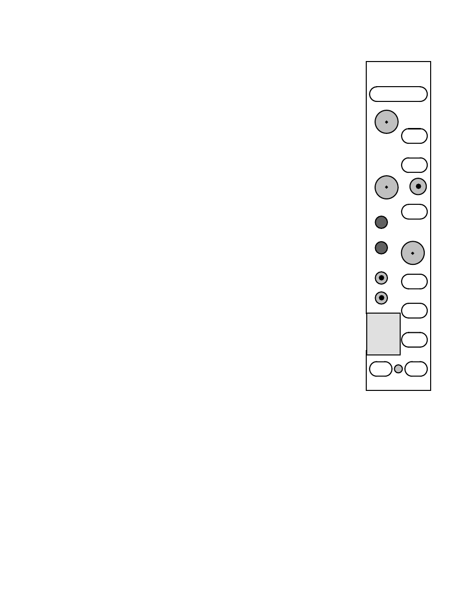
FRONT PANEL
The standard optical input connector is type SC/APC.
There are 3 front panel –20dB RF test points. The receiver T.P. depicts the full
spectrum RF output from the optical receiver. The other 2 test points reflect the rear
panel sub-band outputs. Typical 4.5MHz pilot levels are +14dBmV at the RX T.P. and
+10dBmV at the band 1 T.P. There is no pilot at the band 3 T.P.
For level setting, the accuracy of these band 1 and band 3 test points is ± 1dB.
The power LED should always be on and green. The alarm LED is always on.
It is green unless a failure occurs. It monitors optical input levels, RF AGC, and VCXO
unlock.
The DC test points should be used with a high impedance meter. The optical
input T.P. is calibrated for 1V/mW @ 1310 nm. A correction factor must be applied for
other wavelengths.
The AGC test point reflects the strength of the 4.5MHz pilot signal. A higher
voltage indicates less signal.
REAR PANEL
The rear panel has the 2 RF F output connectors and the 2 SMB connectors that
connect to the LP-DC234. Typical pilot levels are +50dBmV at the pilot connector and
+32dBmV at the RF connector.
FUSE
The module has an internal miniature 3A SB fuse in a holder. The Littelfuse part
number is 0454003. The Olson Technology P/N is 286-000009.
LP-DC212
GND.
OPTICAL
POWER
AGC
ALARM
POWER ON
LP-DC-212
BAND 3
T.P.
RECEIVER
T.P.
BAND 1
T.P.
OPTICAL
INPUT