ONICON F-5100 Inline User Manual
Page 10
11451 Belcher Road South, Largo, FL 33773 • USA • Tel +1 (727) 447-6140 • Fax (727) 442-5699 • [email protected]
F-5100 Inline Thermal Mass Flow Meter Manual 05/15 - 0686-11 / 18332
Page 10
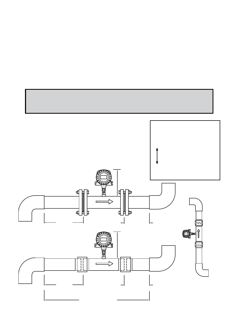
9"Minimum Height
Upstream
Downstream
Available Straight Run
Upstream
Downstream
9"Minimum Height
Meter may be installed in a
vertical pipe with upward or
downward flow
Flow
Flow
Flow
EVALUATING UPSTREAM
PIPING CONDITIONS
Straight Pipe
Single Bend
Pipe Reduction
Multiple Bends in Same Plane
Pipe Expansions
Tees
Multiple Bends Out of Plane
Modulating or Regulating Valve
W
orse
Better
How to Determine the Available Straight Pipe Run:
Locate the longest straight unobstructed section of pipe available. To be unobstructed, the
section of pipe must be free of bends, tees, size transitions, valves or insertion probes of
any kind.
In addition to the information provided above and on the
previous page, the diagrams shown below and the table
shown on the next page should be used as a guide to
identifying the best installation location for the meter.
Required upstream/downstream distances in inches
as measured from the process connections.
GENERAL PRACTICES:
1.
For best results, install the flow meter in a straight run of pipe, free of bends, tees,
valves, transitions and obstructions.
2.
Straight run requirements vary based on the nature of the upstream obstruction.
See the table on page 12 for guidelines in determining upstream straight run
requirements. Depending upon specific location details, more or less straight run
may be required to produce a satisfactory flow profile.
3.
If there is insufficient straight run, allow 80% of the run upstream and 20% of
the run downstream. If the total length of straight run is less than 75% of the
recommended distance, performance may seriously degrade.