ONICON F-5100 Inline User Manual
Page 9
11451 Belcher Road South, Largo, FL 33773 • USA • Tel +1 (727) 447-6140 • Fax (727) 442-5699 • [email protected]
F-5100 Inline Thermal Mass Flow Meter Manual 05/15 - 0686-11 / 18332
Page 9
SECTION 3.0: INSTALLATION
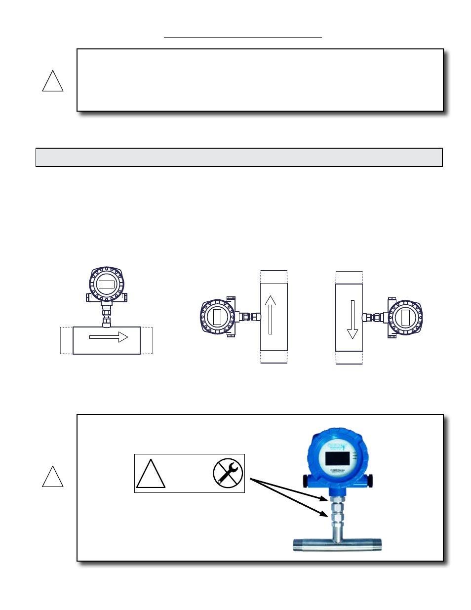
The drawings above illustrate the relationship between the integral display, the flow direction
and the orientation of the meter when installed in the pipe. Contact ONICON for assistance if
this relationship does not allow for viewing the display.
WARNING
This flow meter may be installed in pipes which are under high pressure or pipes filled with
combustible gases. Accidents with these systems can cause serious injury or death. Only persons
experienced with high pressure and/or combustible gas distribution systems and fluid metering
should attempt to install, adjust, or remove the flow meter. Please read all instructions carefully
before attempting to install or service a flow meter.
!
ONICON will be happy to assist with technical recommendations and to provide guidance by phone
or e-mail. On-site field engineering, installation and service are also available at an additional cost.
3.1 INSTALLATION SITE SELECTION
Install the flow meter where it will be accessible for personnel to perform necessary periodic
maintenance. The clearance required for installation is a minimum of 9” from the pipe wall
to the nearest obstruction above the electronics enclosure. Refer to Section 1.5 WORKING
ENVIRONMENT for additional considerations.
ONICON inline style flow meters must also be correctly oriented in the pipe with respect
to the direction of flow. On meters with an integrally mounted display, this will affect the
orientation of the display.
Flow
Flow
Flow
WARNING
!
DO NOT LOOSEN
THESE FITTINGS
WARRANTY VOID
IF REMOVED
!