ONICON F-5100 Inline User Manual
Page 11
11451 Belcher Road South, Largo, FL 33773 • USA • Tel +1 (727) 447-6140 • Fax (727) 442-5699 • [email protected]
F-5100 Inline Thermal Mass Flow Meter Manual 05/15 - 0686-11 / 18332
Page 11
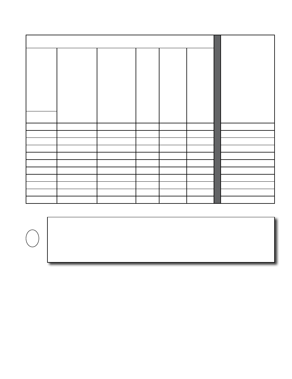
Minimum Straight Run required upstream of flow meter process connection based on
the nature of the upstream obstruction.
Minimum Downstream
Straight Run Required
After Flow Meter
Process Connection
Upstream
Obstructions
Single bend
preceded by ≥ 9
diameters of
straight pipe
Or
Pipe size
reduction in
straight pipe run
Multiple bends
in plane with
< 9 diameters
of straight pipe
between them
Or
Pipe size
expansion in
straight pipe run
Tees
Multiple
bends out
of plane
Modulating
or
Regulating
valves
Or
Roots or
Diaphram
Utility
Meters
Nom. Dia.
¼”
None
2.5”
2.5”
2.5”
2.5”
None
⅜”
1.25”
3.75”
3.75”
3.75”
3.75”
None
½”
1.5”
5”
5”
5”
5”
None
¾”
2.25”
7.5”
7.5”
7.5”
7.5”
1”
1”
3”
10”
10”
10”
10”
1”
1¼”
3.75”
12.5”
12.5”
12.5”
12.5”
2”
1½”
4.5”
15”
15”
15”
15”
2”
2”
6”
20”
20”
20”
20”
4”
2½”
7.5”
25”
25”
25”
25”
7”
3”
9”
30”
30”
30”
30”
9”
4”
12”
40”
40”
40”
40”
12”
IMPORTANT NOTICE
Always use the maximum available straight run. When more than the minimum required straight
run is available place the meter such that the excess straight run is upstream of the meter location.
The flow meter must also be properly installed with respect to the direction of flow. Installing the
meter with the flow arrow pointing in the wrong direction will result in significant errors in the
flow measurement.
i