Sensor, Duct mounted co, Sensor installation – Orion System CO2 Sensor v.1 User Manual
Page 6: Technical guide 6
CO
2
SENSOR
Technical Guide
6
Duct Mounted CO
2
Sensor Installation
Duct Mounted CO
2
Sensor Installation
To install the Duct Mounted CO
2
Sensor, please follow the instructions
below. See Figures 4 & 5 for detailed illustrations of the Duct Mount-
ed CO
2
Sensor and its components.
STEP 1: Find the general location on the side of the Return Air
Duct where you want to mount the CO
2
Sensor. Be sure to locate
the box with the airfl ow in the proper direction per the airfl ow
label. Using the Aspiration Box as a template, draw around it with
a pencil on the duct. Locate the center of the box you have drawn
and mark it. Using a 1
1
/
4
” hole saw, drill a hole in the duct wall
using the center you have just drawn as the drilling point. Insert
the aspiration tube into the hole in the duct and mount the Aspira-
tion Box to the Duct using a power screwdriver to secure the (4)
mounting feet to the Duct wall using the (4) supplied sheet metal
screws.
STEP 2: Remove the Aspiration Box cover from the Aspiration
Box base by loosening the (4) screws that secure it with a Phillips
screwdriver. Using the Phillips screwdriver, loosen the (2) conduit
clamp screws on the conduit clamp assembly located on the side
of the Aspiration Box enough to allow the insertion of the RJ-45
male cable connector(s) and cable(s) through the cable clamp
opening and into the Aspiration Box using the appropriate length
pre-fabricated TSDRSC cable(s) or TSDRSC & FMRSC cable(s)
as required by your application.
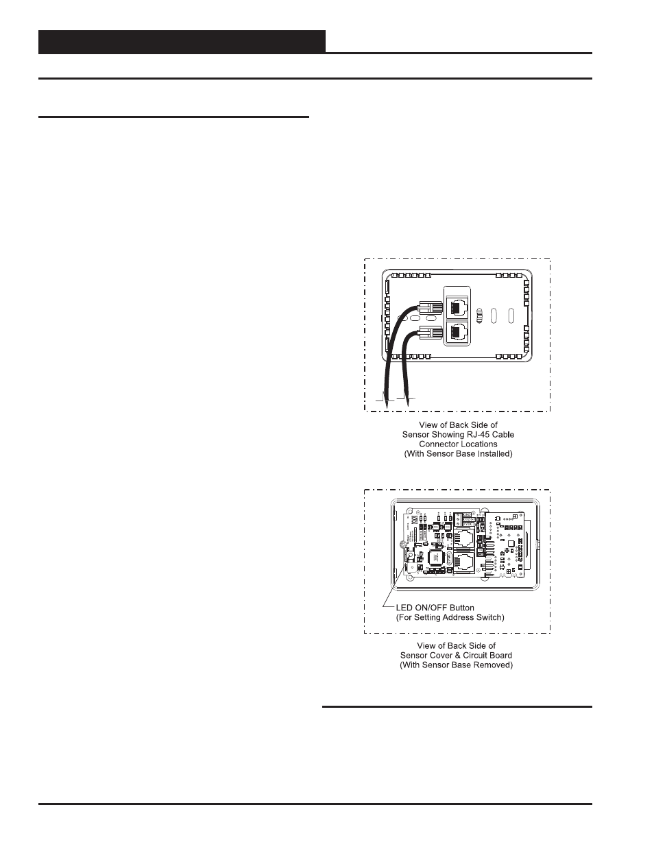
STEP 3: Remove the CO
2
Sensor cover with circuit board by
using the included Allen wrench to loosen the set screw located
at the bottom edge of the CO
2
Sensor assembly and pulling the
Sensor cover with circuit board apart from the Sensor base. Route
the RJ-45 male plug(s) and cable(s) under the Sensor base and
through the rectangular clearance opening in the Sensor base and
then plug the RJ-45 male cable connector(s) into the RJ-45 female
connector(s) on the back of the Sensor circuit board which is at-
tached to the Sensor cover.
STEP 4: The address switch is factory set to “1” which is cor-
rect for Space CO
2
Sensor applications or Return Air CO
2
Sensor
applications. If you have a custom coded application and need to
change the address switch, setting the address switch at this time
is a good idea as it requires taking the Sensor base apart from the
Sensor cover. See page 8 for instructions. It will also require that
you power up the VCM-X Controller that the Sensor is plugged
into to perform the address setting procedures.
STEP 5: After setting the address switch (if required), re-install
the Sensor cover with circuit board to the Sensor base using the
supplied Allen wrench and set screw and re-install the Aspira-
tion Box cover in reverse fashion from how you disassembled it
previously.
STEP 6: Tighten the conduit clamp screws down until the
conduit clamp is gripping the Sensor cable(s) snuggly. Do not
over-tighten the clamp screws as this could damage the cable(s).
Figure 4: CO
2
Sensor Components and Wiring