Sensor, Troubleshooting – Orion System CO2 Sensor v.1 User Manual
Page 9
Advertising
Technical Guide
CO
2
SENSOR
9
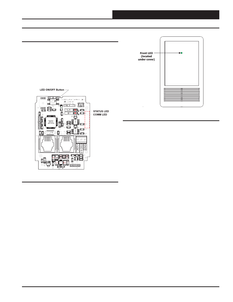
Figure 6: LED ON/OFF Button and Board LEDs
Figure 7: CO
2
Sensor’s Front LED
TB1 Terminal Block (CO
2
Reading)
The TB1 terminal block should only be used to test the sensor when the
sensor cable is plugged into the controller and the sensor and controller
are powered up. Directions: Set the meter for DC volts and connect
the GND probe to the GND terminal and the + probe to the CO
2
0-5
terminal. Look at the output voltage and record it. Multiply the voltage
times 400. The value should match the CO
2
as read on the System Man-
ager TS, Modular System Manager, Modular Service Tool, or Prism. If
the signal doesn’t match the sensor reading, call WattMaster Controls
for a replacement.
Troubleshooting
Advertising
This manual is related to the following products: