E-bus digital room sensor, Appendix – Orion System E-BUS Digital Room v.1 User Manual
Page 10
E-BUS DIGITAL ROOM SENSOR
Operator Interface
10
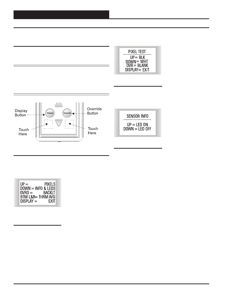
Pixel Test Screen
To select the first option—
Pixels—touch <> while at
the Sensor Configuration &
Test Screen (Figure 12). The
Pixel Test Screen tests the pixels
of the LCD display, allowing
you to make the screen white
with black characters, black
with white characters, or a
black or white screen. To exit
this screen, touch
<Display>
.
Sensor Info & LED Test Screen
To select the second option—
Info & LEDS—touch < >
while at the Sensor Confi gura-
tion & Test Screen (Figure 12).
The Sensor Info & LED Test
Screen shows the version of
software that the sensor is run-
ning and allows you to test the
LEDs that are used on the con-
troller. Touching <> will turn
the LEDs on and touching <>
will turn the LEDs off. To exit
this screen, touch
<Display>
.
Appendix
Sensor Confi guration and Test
Screens
To access the Sensor Confi guration & Test Screens, you fi rst need to
access the Unit Information Screen by touching
<Display>
while at
the Main Display Screen.
NOTE: While in the Sensor Confi guration & Test Screens, the
<Display>
button functions as an exit key to return to the
previous screen or menu. After a few seconds, however,
the sensor will automatically revert to the Main Display
Screen. Refer to Figure 11 when reading the instructions
that follow.
Sensor Confi guration & Test Screen
While the Unit Information
Screen is being displayed, you
can enter the Sensor Confi gura-
tion & Test Screen options by
touching simultaneously below
the
<Display>
and
<Over-
ride>
buttons. (See Figure 11
which shows where to touch to
access this option.)
Figure 11: E-BUS Digital Room Sensor Buttons
Figure 12: Sensor
Confi guration & Test
Screen
Figure 14: Sensor Info &
LED Test Screen
Figure 13: Sensor Info &
LED Test Screen