E-bus digital room sensor, Basic operation, Operator interface 4 – Orion System E-BUS Digital Room v.1 User Manual
Page 4: Sensor operation, Led operation, Back view, Front view, Figure 3: e-bus digital room sensor components
E-BUS DIGITAL ROOM SENSOR
Operator Interface
4
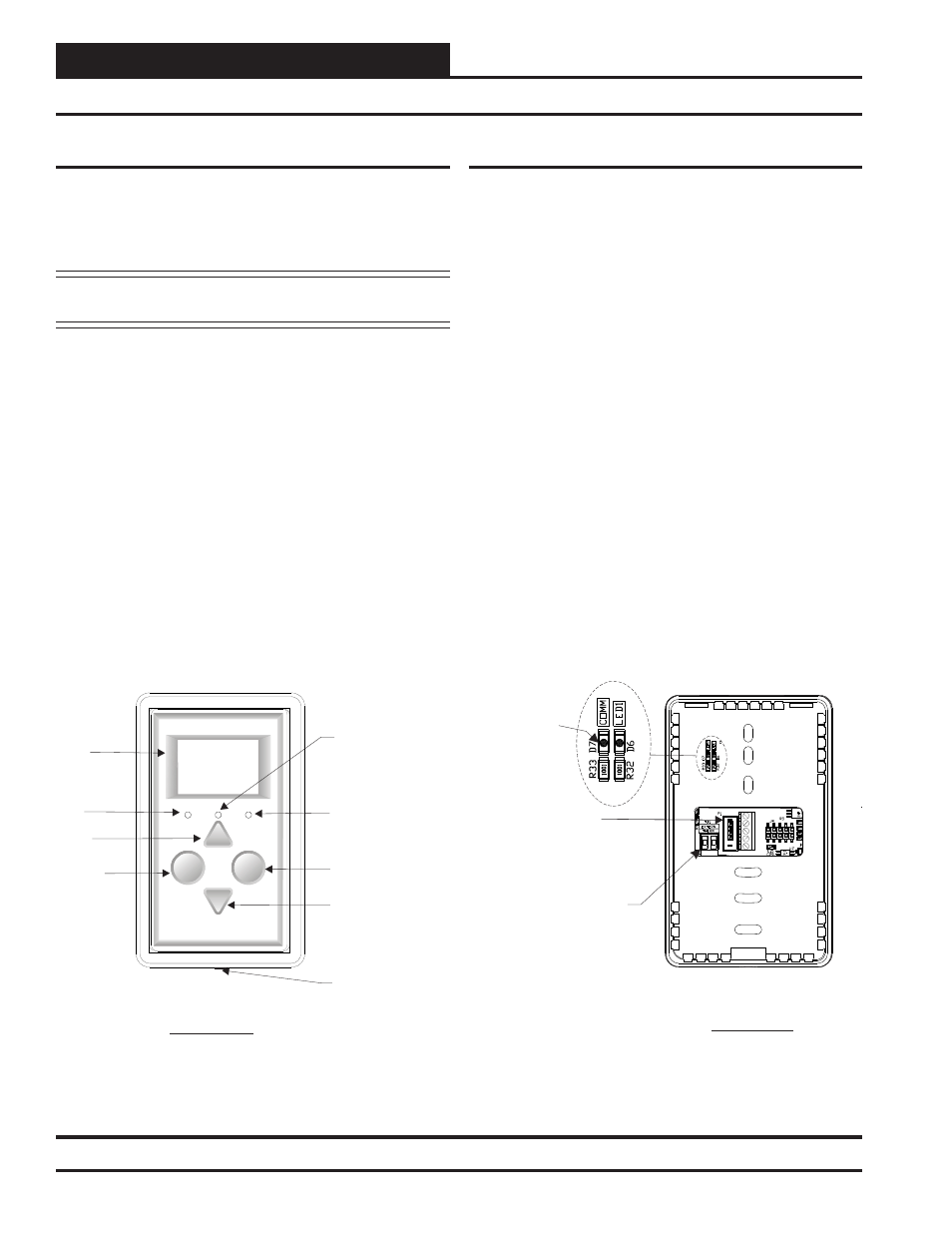
Figure 3: E-BUS Digital Room Sensor Components
Display
Override
OVERRIDE
ALARM
Alarm LED
Sense
LED
Override
LED
Override
Button
Display
Button
Up
Button
Down
Button
LCD
Display
Cover Set
Screw
MI
CR
O
C
H
IP
PI
C
24
H
J
25
6G
P2
06
Back View
Remote Thermistor
Sensor Connector
Front View
E-BUS Cable
Connection
+12Vdc
GND
-COM
SHLD
Comm LED
(Not visible
with back
cover on)
Sensor Operation
When power is fi rst applied to the OE217-02 E-BUS Digital Room
Sensor, the sensor will display the Current Room Temperature and the
current setting of the slide offset. The OE217-03 model will also display
Relative Humidity.
NOTE: The sensor readings are not accurate until the controller
that the sensor is connected to is done calibrating.
The sensor has 4 buttons—
<Display>
,
<Override>
,
<Up>
, and
<Down>
. You can also access certain functions by touching the area
below the
<Display>
and
<Override>
buttons. The sensor has 3
LEDs—one to indicate an Override, one to indicate an Alarm, and one
to indicate that a button has been pressed. See Figure 3 for LED and
Button Descriptions.
An icon for the current mode of operation will appear in the sensor
display. The operation mode icons are a Snowfl ake for Cooling Mode,
a Flame for Heating Mode, a Fan in motion for Vent Mode, and a Moon
for Unoccupied Mode. When the unit is in Unoccupied Mode, the
screen’s background will turn dark. See Figure 9, page 7 for examples
of operation modes.
Basic Operation
LED Operation
Refer to Figure 3 below for LED locations.
Alarm LED: The Alarm LED will blink when there is an alarm from
the Controller.
Sense LED: The Sense LED will blink when the sensor gets a valid
touch.
Override LED: The Override LED is inoperable when in Occupied
Mode. In Unoccupied Mode, if you touch the
<Override>
button, the
Override LED will blink, indicating an override request. The Control-
ler will respond by sending the unit into override. The Override LED
will then stay on for the duration of the Override. Any time the Unit
is in Override, you can request to cancel the override by touching the
<Override>
button, and the Override LED will blink. The Unit will
then cancel the override. The Override LED will then turn off.
Comm LED: The Comm LED located on the back of the sensor
blinks on whenever communications are sensed.