E-bus digital room sensor, Appendix - e-bus digital room sensor wiring, Operator interface 12 – Orion System E-BUS Digital Room v.1 User Manual
Page 12: Vcb-x controller e-bus digital room sensor, Ebc e-bus cable
E-BUS DIGITAL ROOM SENSOR
Operator Interface
12
Appendix - E-BUS Digital Room Sensor Wiring
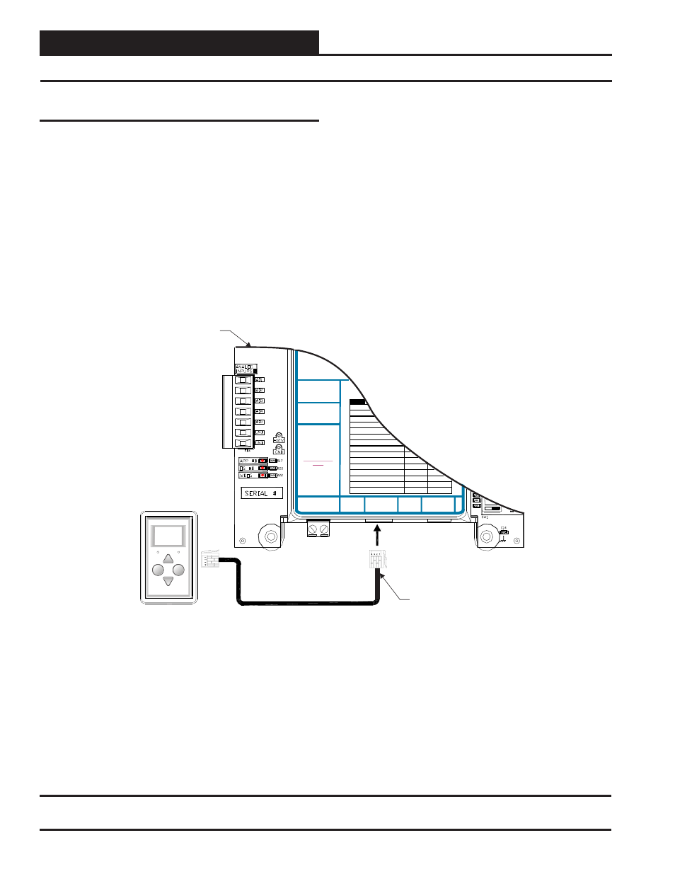
E-BUS Digital Room Sensor
The OE217-02, OE217-03, or OE217-04 E-BUS Digital Room Sensor
connects to the VCB-X or VCC-X Controller with the EBC E-BUS
expansion cable.
The Digital Room Sensor should be mounted at approximately 5 Ft.
above the fl oor on the wall in an area that does not have drafts or is
exposed to direct sunlight. See Figure 18 for wiring details.
VCB-X Controller
E-BUS Digital Room Sensor
Display
Override
OVERRIDE
ALARM
EBC E-BUS
Cable
NOTE: When Only The E-BUS
Connects Directly To The
Controller Using A
Of The Appropriate Length.
Digital Room Sensor Is Used, It
VCB-X
n EBC E-BUS
Cable
Mount At Least 5 Feet Above Floor.
See
on page 13 For
Connection When A Wall-Mounted
E-BUS C
Sensor
Is Also Used.
Figure 19
O
2
24 VAC POWER
ONLY
WARNING!
POLARITY MUST
BE OBSERVED
OR THE
CONTROLLER
WILL BE
DAMAGED
AO2
AO3
TR1
= SC
= DIGITAL CO
TRIAC OUTPUT
LED N
M
NORMAL
SAT FAIL
OAT FAIL
SPC FAIL
MECH COOL FAIL
MECH HEAT FAIL
FAN PROOF FAIL
DIRTY FILTER
EMERGENCY SHUTDOWN
LOW SAT
1
HIGH SAT
2
CONT. TEMP COOL FAIL
3
CONT. TEMP HEAT FAIL
4
4
PUSH BUTTON OVR
1
5
OUTPUT FORCE ACTIVE
0
6
WattMaster Label
#LB102093-01-A
Rev.: 1C
E-BUS
EXPANSION
E-BUS
EXPANSION
24 VAC
INPUT
=
Figure 18: OE217-02, OE217-03 & OE217-04 – E-BUS Digital Room Sensor Wiring
Revised 05/01/12